| Transition Temperature | 307.6 K |
|---|---|
| Propagation Vector | k1 (0, 0, 0) |
| Parent Space Group | R-3c (#167) |
| Magnetic Space Group | C2'/c (#15.87) |
| Magnetic Point Group | 2'/m (5.3.14) |
| Lattice Parameters | 4.95700 4.95700 13.59230 90.00 90.00 120.00 |
|---|---|
| DOI | 10.1103/physrevb.54.r12681 |
| Reference | M. Fiebig, D. Frohlich and H.J. Thiele, Physical Review B (1996) 54 R12681-R12684. |
| Label | Element | Mx | My | Mz | |M| |
|---|---|---|---|---|---|
| Cr1 | Cr | -1. | 0.0 | 0.0 | 1.00 |
Determination of spin direction in the spin-flop phase of \( Cr_{2}O_{3} \)
M. Fiebig, D. Fröhlich, and H.-J. Thiele
Institut für Physik, Universität Dortmund, D-44221 Dortmund, Germany
(Received 9 August 1996)
Despite a number of experimental investigations the determination of the orientation of spins in the spin-flop phase of antiferromagnetic (AFM) \( Cr_{2}O_{3} \) is still an open problem. We show that one has to take into account magnetic domains in order to clarify the magnetic structure. Domains can be distinguished optically by the interference of time-invariant and time-noninvariant contributions to the second harmonic. With use of this technique the domain structure in the spin-flop phase of \( Cr_{2}O_{3} \) is determined with high resolution in only a few minutes. Three images with light polarized parallel to the respective twofold axes (y axes) of the crystal are sufficient to identify the six possible domains. It was found that the AFM vector is oriented along the y axes of the crystal. [S0163-1829(96)51342-1]
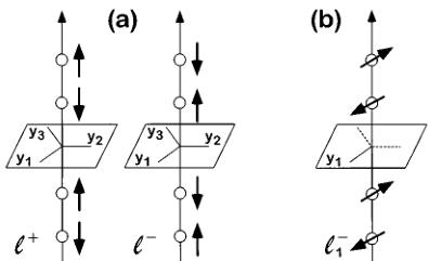
The magnetic structure of \( Cr_{2}O_{3} \) in zero magnetic field is by now well known. Below the Néel temperature ( \( T_{N}=307.6~K \) ) the four chromium spins in the unit cell are aligned along the threefold axis (z axis) of the crystal. Because of the antiferromagnetic (AFM) order of the spins \( ^{1} \) the crystal loses both space- and time-reversal symmetry below \( T_{N} \) . This leads to \( 180^{\circ} \) domains which can be transformed into each other by application of space or time inversion [Fig. 1(a)]. Recently it was shown that this symmetry reduction leads to rather spectacular nonlinear optical effects \( ^{2} \) which can be used for high-resolution topography of magnetic domains. \( ^{3} \) It is further known that in sufficiently high magnetic fields along the z axis the spins flop into the basal plane maintaining their AFM order [Fig. 1(b)]. \( ^{4,5} \) This so-called spin flop is a first-order transition which occurs at a critical field \( B_{c}=5.8~T \) (below 90 K). Up to now there is disagreement if there exists a preferred direction of spins within the basal plane. Up to now the direction of magnetic moments in the spin-flop phase was derived from the investigation of the magnetoelectric (ME) effect. A ME medium becomes polarized when it is placed in a magnetic field. It becomes magnetized when it is placed in an electric field. \( ^{6} \) The effect shows a linear dependence on the applied field (magnetic or electric). It is described by a time-non-invariant axial tensor ( \( \alpha_{ij} \) ) of second rank. For a recent review on crystal optics of magnetoelectrics we refer to Ref. 7. The disappearance of various components of ( \( \alpha_{ij} \) ) can be derived from the magnetic symmetry of the crystal \( ^{6,8} \) which is determined by the orientation of spins. From the magnetic-field dependence of selected components of ( \( \alpha_{ij} \) ) the authors of Refs. 8 and 9 came to the conclusion that the spins are aligned in the glide planes along the x axes. They do not preclude, however, that the anisotropy in the easy plane (xy plane) might be too small to lead to a definite orientation of the AFM vector. Contrary to this result, the authors of Refs. 10 and 11 claim that the spins align along the twofold axes (y axes).
In this paper we show that one has to take into account the existence of magnetic domains in order to clarify the magnetic structure. We present a technique for the investigation of spin-flopped \( Cr_{2}O_{3} \) . From nonlinear optical spectroscopy and topography we derive its magnetic structure and thus the orientation of spins for \( B > B_{C} \) .
In a nonlinear optical transition two or more electromagnetic fields are coupled to the nonlinear source term in the wave equation. In nonmagnetic crystals all contributions to the nonlinear signal are invariant under application of the time-reversal operation. The coupling is macroscopically described by the time-invariant (reciprocal, i type) nonlinear susceptibilities \( \chi_{ijk\ldots}(i) \) . In magnetic crystals, however, additional contributions to the nonlinear signal exist which change sign under the time-reversal operation. They are described by time-noninvariant (nonreciprocal, c type) nonlinear susceptibilities \( \chi_{ijk\ldots}(c) \) . \( ^{12} \) Below the transition temperature reciprocal and nonreciprocal contributions may interfere. For a given polarization of the electromagnetic fields the nonreciprocal part is different in different domains, whereas the reciprocal part of the source term is constant all over the crystal. Thus, magnetic domains may be distinguished optically. In the case of second harmonic generation this technique has recently been applied to \( Cr_{2}O_{3} \) . \( ^{2,3} \)
Above the Néel temperature, \( Cr_{2}O_{3} \) crystallizes in the centrosymmetric point group \( \overline{3}m \) . \( ^{12,13} \) Polar i tensors of odd rank are forbidden but axial i tensors of odd rank are allowed

FIG. 1. Schematic of spin ordering in \( Cr_{2}O_{3} \) : In zero magnetic field the four spins in the unit cell order in two ways \( (\mathcal{S}^{+},-) \) corresponding to different \( 180^{\circ} \) domains (a). In the spin-flop phase (magnetic field \( B > 5.8~T \) for \( T < 90~K \) ) spins are oriented in the basal plane along one out of three y axes of the crystal maintaining their AFM order. This gives rise to six possible domains \( (\mathcal{S}_{1,2,3}^{+}) \) out of which one \( (\mathcal{S}_{1}^{-}) \) is shown (b).
in this point group. \( ^{12} \) Thus, above \( T_{N} \) nonlinear electric-dipole effects due to the susceptibility \( \chi_{ijk}^{e} \) (polar i tensor) are forbidden, but magnetic-dipole effects due to \( \chi_{ijk}^{m} \) (axial i tensor) are allowed. Though being allowed, quadrupole contributions to the second harmonic (SH) are neglected since they have not been observed in \( Cr_{2}O_{3} \) up to now. Below \( T_{N} \) , space- and time-reversal symmetry operations are simultaneously broken by the AFM ordering of spins. Therefore polar c tensors of odd rank are now also allowed. \( ^{12} \) Thus, below \( T_{N} \) magnetic-dipole effects due to \( \chi_{ijk}^{m} \) (axial i tensor) and electric-dipole effects due to \( \chi_{ijk}^{e} \) (polar c tensor) can interfere. Magnetic dipole transitions are usually neglected in comparison with electric dipole transitions. In case of d-d transitions in magnetics, however, the respective contributions may be comparable. \( ^{2,14} \)
In the wave equation for the electric field the magnetic- and electric-dipole contributions lead to source terms \( \mu_{0}\nabla\times(\partial\mathbf{M}_{NL}/\partial t) \) and \( \mu_{0}(\partial^{2}\mathbf{P}_{NL}/\partial t^{2}) \) for SH, respectively. \( ^{2,15,16} \) The nonlinear magnetic and electric polarizations \( M_{NL} \) and \( P_{NL} \) are determined by the components of the nonlinear susceptibilities \( \chi_{ijk}^{m}(i) \) and \( \chi_{ijk}^{e}(c) \) , respectively. The tensor components of the reciprocal contributions do not couple to the magnetic ordering of the crystal. Thus, they are determined by the crystallographic point group \( \overline{3}m \) . Tensor components of nonreciprocal contributions, however, depend on the orientation of the AFM vector L and hence on the magnetic point group of the crystal. In zero magnetic field there is \( L\|z \) . The magnetic symmetry is \( \overline{3}m \) and the crystal can exhibit two different \( 180^{\circ} \) domains \( (\swarrow,+,\swarrow-) \) which can be transformed into each other by the time- or space-reversal operation. In the spin-flop phase the magnetic symmetry is lowered to \( 2/m \) (if \( L\|y \) ) or \( 2/m \) (if \( L\|x \) ) provided that the anisotropy is large enough to prevent an arbitrary orientation of L in the easy plane. The threefold rotation axis (z axis) is lost due to the reorientation of spins [Fig. 1(b)]. The three sets of x and y axes in the crystal are thus no longer equivalent. Each of the respective coordinate systems corresponds to one out of three possible orientations of the AFM vector. The three different orientations of L correspond to three orientational domains \( (\swarrow,+,\swarrow,-,\swarrow) \) . Since they arise for either of the two \( 180^{\circ} \) domains of the sample, there are in total six different domains \( (\swarrow,+,-,3) \) possible due to the reduction of symmetry by the spin flop.
Measurements of the ME effect yield no spatial resolution. In order to determine the magnetic-field dependence of \( \hat{\alpha} \) one thus has to use a single-domain sample which is carefully oriented in the external magnetic field. \( ^{[11]} \) In general, however, samples are multidomain and the orientation of the Cartesian axes is defined only locally. Though the components of the ME tensor \( \hat{\alpha} \) are sensitive to the magnetic symmetry it is not possible in this case to derive the direction of L from the magnetic-field dependence of \( \hat{\alpha} \) . Even if samples have been annealed \( ^{[17]} \) in order to achieve a single-domain state with regard to \( 180^{\circ} \) domains in zero magnetic field, they can be multidomain with regard to the different orientational domains which arise after the spin-flop transition. In preceding publications \( ^{[8-11]} \) orientational domains have not been taken into account. It was not discussed that there remains only one x axis and one y axis for each domain. We thus conclude that up to now only linear combinations of various \( \alpha_{ij} \) ( \( ij \neq zz \) ) have been measured in a magnetic field \( B > B_{C} \) . From these measurements the orientation of the AFM vector cannot be derived. Only \( \alpha_{zz} \) is not mixed with other components of the ME tensor in multidomain samples. It vanishes, however, due to magnetic symmetry (in case \( L \| x \) ) or due to additional degeneracy (in case \( L \| y \) ) if the magnetic field is properly oriented along the z axis. \( ^{[11]} \)
nations of various \( \alpha_{ij} \) ( \( ij \neq zz \) ), have been measured in a magnetic field \( B > B_{C} \) . From these measurement the orientation of the AFM vector cannot be derived. Only \( \alpha_{zz} \neq 0 \) is not mixed with other components of the ME tensor in multidomain samples. It vanishes. However, due to magnetic symmetry (in case \( L \| x \) ) or due to the additional degeneracy (in case \( L \| y \) ) if the magnetic field is correctly oriented along the z axis. \( ^{11} \)
Contrary to ME experiments, SH topography yields a high spatial resolution. \( ^{3} \) Hence, this technique is suitable for the investigation of AFM domains in the spin-flop phase of \( Cr_{2}O_{3} \) . The six possible domains are distinguished by the two-photon selection rules which can be derived from Table I. Since the selection rules for the magnetic point groups 2/m and 2/m are different it is even possible to determine along which of the three x or y axes L is oriented.
In the experiment a frequency-tripled Nd-doped yttrium-aluminum-garnet (YAG) laser is used for pumping an optical parametric oscillator (OPO). The infrared beam from the OPO is enlarged to the size of the sample by means of a telescope. The polarization of the beam is set by use of a half-wave plate. SH light from the sample is projected on a liquid-nitrogen-cooled CCD camera. Scattered laser light is suppressed by use of optical filters. The bulk samples (size about \( 10 \, mm^2 \) ) are x-ray oriented. They are cut perpendicular to the optical axis from boules of \( Cr_2O_3 \) grown by the Verneuil method. Light is incident along the threefold axis of the crystals. Samples are mounted in a liquid-helium cryostat at \( T = 1.8 \, K \) in a split-coil magnet. Fields of up to 6.6 T are applied along the threefold axis. Exposure times are in the order of a few minutes. The spatial resolution is about \( 10 \, \mum \) .
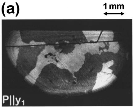
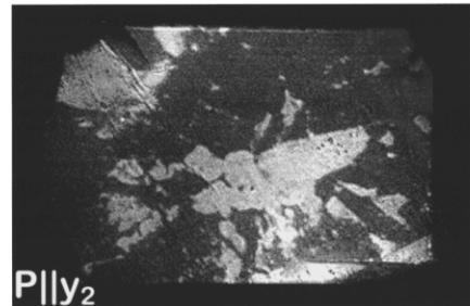
Figure 2 shows two sets of images which were gained from two samples in the spin-flop phase with light polarized parallel to the three twofold axes \( y_{1,2,3} \) of the crystal. Since the images taken with \( y_{1} \) -, \( y_{2} \) -, and \( y_{3} \) -polarized light differ, the SH signal must depend on the magnetic ordering of spins which breaks the threefold symmetry of the crystal in the
(a)

(b)


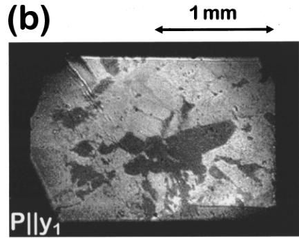
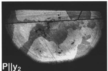
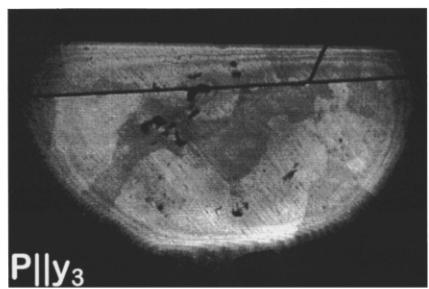
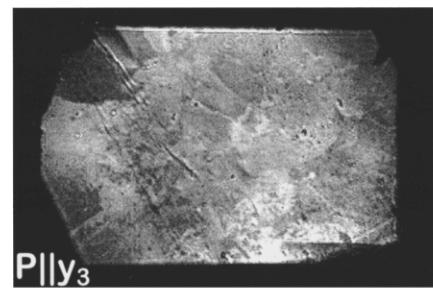
FIG. 2. Domains of two \( Cr_{2}O_{3} \) samples in the spin-flop phase. The images of sample No. 1 [Fig. 2(a)] and sample No. 2 [Fig. 2(b)] were taken with light polarized parallel to each of the three twofold axes \( y_{1,2,3} \) of the crystal. Excitation energy \( E_{SH}=2.22 \) eV, magnetic field B=6.5 T, temperature T=1.8 K, exposure time t=5 min.
spin-flop phase. The distribution of dark and bright regions of the samples (Fig. 2) can be fully understood with the aid of Table I: For each domain the angle between the local x or y axis, which is determined by the direction of L, and the polarization \( y_{1,2,3} \) of the incoming light is \( \phi=\pm120^{\circ} \) in two images and \( \phi=0^{\circ} \) in the remaining image. If the AFM vector is oriented parallel to one of the twofold axes ( \( L\|y \) ) this leads to identical SH intensities in the first two cases and to a different brightness in the latter case. If the AFM vector is oriented perpendicular to one of the twofold axes ( \( L\|x \) ) the intensity of the SH light emitted from one domain would be different in all three cases while the brightness of the domains \( \nearrow^{+,-} \) for \( \phi=+120^{\circ} \) and \( \nearrow^{-,+} \) for \( \phi=-120^{\circ} \) would be equal.
In Fig. 2(a) two of the images \( (\mathbf{P}\|\mathbf{y}_{2}, \mathbf{P}\|\mathbf{y}_{3}) \) look alike. They exhibit a weak contrast between neighboring domains whereas in the remaining image \( (\mathbf{P}\|\mathbf{y}_{1}) \) the contrast is much stronger and reversed. Thus, this sample exhibits two \( 180^{\circ} \) domains \( (\swarrow_{1}^{+} \) and \( \swarrow_{1}^{-}) \) with the AFM vector oriented along one specific twofold axis of the crystal \( (\mathcal{L}\|\mathbf{y}_{1}) \) .
In Fig. 2(b) each region of the sample is either bright on two of the images or dark on the remaining one. The SH intensity emitted from a bright region does not depend on the polarization of the incoming light. As in Fig. 2(a) the two images with equal brightness in any given region indicate that for these images the angle between the local y axis and the polarization of the incoming light is \( \pm120^{\circ} \) . The orientation of the AFM vector in this region is then given by the respective y polarization of the incident light leading to low SH intensity. Contrary to Fig. 2(a), the regions of the sample
in Fig. 2(b) always occur as bright regions in two images and dark in the remaining image, but never in the opposite case (low intensity twice and high intensity once). Therefore, in this sample, only one \( 180^{\circ} \) domain is present but with all three orientations of the AFM vector. The corresponding domains are \( \angle_{1}^{+} \) , \( \angle_{2}^{+} \) , and \( \angle_{3}^{+} \) .
Remarkably, the sample exhibits three orientational domains in the spin-flop phase though it was found to be single domain below the critical field \( B_{C} \) . ME annealing, which has been applied by various groups \( ^{8,9} \) in order to achieve single-domain samples, is thus only suitable in zero magnetic field. When \( B_{C} \) is exceeded, orientational domains as a new type of domain become allowed and the single-domain state is lost because the annealing fields are no longer present. Actually, when the magnetic field \( B > B_{C} \) is turned off, one observes that the spin flop can lead to an irreversible change of the zero-field \( 180^{\circ} \) domain structure. We are able to achieve a single-domain state in the spin-flop phase by tilting the sample in the magnetic field by more than \( 7^{\circ} \) . In this case the anisotropy in the xy plane is overcome by the magnetic-field component perpendicular to the z axis and the AFM vector can be oriented arbitrarily. When the sample is tilted back orientational domains reappear.
As a further test of the orientation of the AFM vector in the spin-flop phase we measured the SH spectrum of \( Cr_{2}O_{3} \) in the energy interval from 1.8–2.9 eV with circularly polarized light. With use of Table I one can transform the two-photon selection rules into a circular basis and thus derive the SH intensity I for right \( (\sigma_{+}) \) and left \( (\sigma_{-}) \) circularly polarized light for each of the six domains in the spin-flop phase. If \( L\|z \) or \( L\|x \) the intensity difference \( \Delta I = I(\sigma_{+}) - I(\sigma_{-}) \) is given by a sum of products \( \chi_{ijk}^{m}(i)\chi_{i'j'k'}^{e}(c) \) which is a linear function of the AFM order parameter. \( ^{14} \) If \( L\|y \) , however, one gets \( \Delta I = 0 \) . For the experiments the laser beam is now focused on one spot of the sample. The CCD camera is replaced by a monochromator for suppression of scattered laser light and a photomultiplier as a detector of the SH signal. Below the critical field \( B_{C} \) a ratio of up to 50:1 is observed between different domains or
\( ^{1} \) L. M. Corliss, J. M. Hastings, R. Nathans, and G. Shirane, J. Appl. Phys. 36, 1099 (1965).
\( ^{2} \) M. Feibig, D. Fröhlich, B. B. Krichevtsov, and R. V. Pisarev, Phys. Rev. Lett. 73, 2127 (1994).
\( ^{3} \) M. Fiebig, D. Fröhlich, G. Sluyterman v.L., and R. V. Pisarev, Appl. Phys. Lett. 66, 2906 (1995).
\( ^{4} \) R. D. Yacovitch and Y. Shapira, Physica (Utrecht) B+C 86-88, 1126 (1977).
\( ^{5} \) S. Foner, Phys. Rev. 130, 183 (1963).
\( ^{6} \) T.H. O'Dell, The Electrodynamics of Magneto-Electric Media (North-Holland, Amsterdam, 1970).
\( ^{7} \) Proceedings of the 2nd International Conference on Magnetoelectric Interaction Phenomena in Crystals, Ascona, Switzerland, 1993, edited by H. Grimmer et al. [Ferroelectrics 161 (1994); Ferroelectrics 162 (1994)].
\( ^{8} \) J. Ohtani and K. Kohn, J. Phys. Soc. Jpn. 53, 3744 (1984).
\( ^{9} \) H. Wiegelmann, A. G. M. Jansen, P. Wyder, J.-P. Rivera, and H.
circular polarizations of the incoming light. \( ^{2} \) Above \( B_{C} \) the polarization dependence vanishes completely in agreement with the results of SH domain topography. Like Belov et al. \( ^{11} \) one finds that the experiment is rather sensitive to the alignment of the crystalline z axis with respect to the applied magnetic field. A deviation of \( >0.1^{\circ} \) already leads to a difference \( I(\sigma_{+})-I(\sigma_{-}) \) exceeding 50% for some SH energies. Figure 2 was gained with a misalignment of \( 1-2^{\circ} \) at \( E_{SH}=2.22 \) eV. For this SH energy the deviation is not that critical. It is, however, responsible for the slight difference between the images in Fig. 2(a) taken with \( y_{2} \) - and \( y_{3} \) -polarized light. In addition, it induces a nonvanishing component \( \alpha_{zz} \) of the ME tensor, \( ^{11} \) which might lead to the conclusion that L is parallel to the x axis in spin-flopped \( Cr_{2}O_{3} \) . \( ^{8,9} \)
In conclusion, we have shown that interference of reciprocal and nonreciprocal contributions to optical second harmonic generation is up to now the only suitable mechanism for the investigation of magnetic domains in the spin-flop phase of \( Cr_{2}O_{3} \) . Preceeding publications concerning this question are contradictory since the existence of orientational domains was neglected. Three images with linearly polarized light allow to distinguish the six possible domains. A symmetry analysis of the images shows that in the spin-flop phase magnetic moments are oriented along the twofold axes (y axes) of the crystal. The result is confirmed by spectroscopic measurements of the second harmonic. The determination of the magnetic symmetry in the spin-flop phase of \( Cr_{2}O_{3} \) is just one application of this spectroscopic method. The interference of “magnetic” nonreciprocal and “nonmagnetic” reciprocal contributions to the source term in the nonlinear wave equation is allowed in magnetic crystals with arbitrary magnetic symmetry. Magnetic structures can thus be investigated by very simple optical experiments.
We thank Professor R. V. Pisarev for the samples and many stimulating discussions. The financial support by the Deutsche Forschungsgemeinschaft and the Gradiiertenkolleg “Festkörperspektroskopie” is greatly appreciated.
Schmid, Ferroelectrics 162, 141 (1994).
\( ^{10} \) Y. F. Popov, Z. A. Kazei, and A. M. Kadomtseva, Pis'ma Zh. Eksp. Teor. Fiz. 55, 238 (1992) [JETP Lett. 55, 238 (1992)].
\( ^{11} \) D. V. Belov, G. P. Vorob'ev, A. M. Kadomtseva, and Y. F. Popov, Pis'ma Zh. Eksp. Teor. Fiz. 58, 603 (1993) [JETP Lett. 58, 579 (1993)].
\( ^{12} \) R.R. Birss, Symmetry and Magnetism (North Holland, Amsterdam, 1966).
\( ^{13} \) I. E. Dzyaloshinskii, Zh. Eksp. Teor. Fiz. 37, 881 (1959) [Sov. Phys. JETP 10, 628 (1959)].
\( ^{14} \) V. N. Muthukumar, R. Valenti, and C. Gros, Phys. Rev. Lett. 75, 14 (1995); Phys. Rev. B 54, 433 (1996).
\( ^{15} \) P.S. Pershan, Phys. Rev. 130, 919 (1963).
\( ^{16} \) E. B. Graham and R. E. Raab, Philos. Mag. B66, 269 (1992).
\( ^{17} \) B. B. Krichevtsov, V. V. Pavlov, and R. V. Pisarev, Zh. Eksp. Teor. Fiz. 94, 284 (1988) [Sov. Phys. JETP 67, 378 (1988)].
 p1_0.jpg
 p3_0.jpg
 p3_1.jpg
 p3_2.jpg
 p3_3.jpg
 p3_4.jpg
 p3_5.jpg