| Transition Temperature | 127 K |
|---|---|
| Propagation Vector | k1 (0, 0, 0) |
| Parent Space Group | Pnma (#62) |
| Magnetic Space Group | Pnm'a (#62.444) |
| Magnetic Point Group | m'mm (8.3.26) |
| Lattice Parameters | 7.6890 14.8196 7.7800 90.0000 90.0000 90.0000 |
|---|---|
| DOI | 10.1103/physrevb.71.214408 |
| Reference | L. Tan, A. Kreyssig, J.W. Kim, A.I. Goldman, R.J. McQueeney, D. Wermeille, B. Sieve, T.A. Lograsso, D.L. Schlagel, S.L. Budko, V.K. Pecharsky and K.A. Gschneidner, Physical Review B (2005) 71. |
| Label | Element | Mx | My | Mz | |M| |
|---|---|---|---|---|---|
| Gd1 | Gd | 0.0 | 0.0 | 1. | 1.00 |
| Gd2 | Gd | 0.0 | 0.0 | 1. | 1.00 |
| Gd3 | Gd | 0.0 | 0.0 | 1. | 1.00 |
Magnetic structure of \( Gd_{5}Ge_{4} \)
L. Tan, \( ^{1} \) A. Kreyssig, \( ^{1} \) J. W. Kim, \( ^{1} \) A. I. Goldman, \( ^{1,*} \) R. J. McQueeney, \( ^{1} \) D. Wermeille, \( ^{2} \) B. Sieve, \( ^{1} \) T. A. Lograsso, \( ^{2} \)
D. L. Schlagel, \( ^{2} \) S. L. Budko, \( ^{1} \) V. K. Pecharsky, \( ^{3} \) and K. A. Gschneidner, Jr. \( ^{3} \)
\( ^{1} \) Department of Physics and Astronomy, Iowa State University, Ames, Iowa 50011, USA
\( ^{2} \) Ames Laboratory, USDOE, Ames, Iowa 50011, USA
\( ^{3} \) Department of Materials Science and Engineering, Iowa State University, Ames, Iowa 50011, USA (Received 10 February 2005; published 8 June 2005)
\( Gd_{5}Ge_{4} \) crystallizes in the orthorhombic space group Pnma, and orders antiferromagnetically below the Néel temperature \( T_{N}\sim127 \) K. We have employed x-ray resonant magnetic scattering to elucidate the details of the magnetic structure. The magnetic unit cell is the same as the chemical unit cell. From azimuth scans and the Q dependence of the magnetic scattering, all three Gd sites in the structure were determined to be in the same magnetic space group Pnm'a. The magnetic moments are primarily aligned along the c axis and the c components of the magnetic moments at the three different sites are equal. The ferromagnetic Gd-rich slabs are stacked antiferromagnetically along the b direction.
DOI: 10.1103/PhysRevB.71.214408
PACS number(s): 75.25.+z, 75.30.-m, 75.50.-y
I. INTRODUCTION
The \( \mathrm{Gd}_{5}(\mathrm{Si}_{x}\mathrm{Ge}_{1-x})_{4} \) alloys have received attention recently because of their unusually strong magnetocaloric, \( ^{1,2} \) magnetostrictive, \( ^{3,4} \) and magnetoresistive \( ^{5-7} \) properties when \( x \leqslant 0.5 \) . All of these properties appear to be related to a first order magnetic transition accompanied by a martensiticlike structural change. \( ^{8} \)
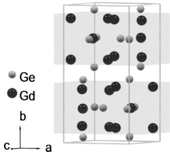
One of the endmembers of this series of compounds, \( Gd_{5}Ge_{4} \) , crystallizes in the \( Sm_{5}Ge_{4} \) -type orthorhombic structure with space group Pnma, and lattice constants \( a = 7.6838 \, \AA \) , \( b = 14.7930 \, \AA \) , and \( c = 7.7628 \, \AA \) at \( T = 6 \, K \) . The Gd ions are located at one 4c Wyckoff site and two inequivalent 8d Wyckoff sites. They form two Gd-rich slabs, separated by sheets of Ge as shown in Fig. 1. \( ^{10} \) Below the Néel temperature, \( T_{N} \sim 127 \, K \) , a second-order transition occurs where the Gd moments order antiferromagnetically. A first order magnetic transition from the antiferromagnetic phase (AFM) to a ferromagnetic phase (FM) occurs in an applied magnetic field of 18 kOe at \( T = 4.5 \, K \) . \( ^{10} \) Alternatively, when Si is substituted for Ge in \( \mathrm{Gd}_{5}(\mathrm{Si}_{x}\mathrm{Ge}_{l-x})_{4} \) up to x < 0.2, a similar AFM \( \rightarrow \) FM first order transition occurs upon cooling in zero field. \( ^{11} \) In both cases, the magnetic transition occurs concomitantly with a structural transition where the slabs shift relative to one another in the a direction. \( ^{11,9} \) From magnetization measurements and x-ray structural studies, it has been proposed that the Gd magnetic moments are ferromagnetically aligned within the slabs, while the coupling between slabs can be antiferromagnetic or ferromagnetic. This indicates the presence of strong magnetoelastic coupling.
Details of the microscopic magnetic structure of \( Gd_{5}Ge_{4} \) or, in fact, any of the \( \mathrm{Gd}_{5}(\mathrm{Si}_{x}\mathrm{Ge}_{{1-x}})_{4} \) alloys have not been determined largely due to the large neutron absorption cross section of naturally occurring Gd. The aim of the present measurement is to elucidate the antiferromagnetic structure of \( Gd_{5}Ge_{4} \) using x-ray resonant magnetic scattering (XRMS).
II. EXPERIMENTAL DETAILS
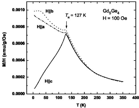
Single crystals of \( Gd_{5}Ge_{4} \) were grown using the Bridgman technique. \( ^{[12]} \) For the XRMS measurements, single crystals were extracted from the ingot and prepared with polished surfaces perpendicular to the crystallographic a and b axes, with a size of approximately \( 2 mm \times 2 mm \) . The temperature dependence of the magnetization was measured with a SQUID magnetometer and is shown in Fig. 2. These data clearly show an antiferromagnetic transition at \( T_{N}=127 K \) , and indicate that the magnetic moment direction is likely along the c axis since the magnetization in c direction decreases to zero as temperature decreases to the base temperature. These results are in agreement with previous magnetization measurements. \( ^{[13]} \)
The XRMS experiment was performed on the 6ID-B beamline in the MUCAT sector at the Advanced Photon Source at the Gd \( L_{II} \) absorption edge (E=7.934 keV). The incident radiation was linearly polarized perpendicular to the vertical scattering plane ( \( \sigma \) polarized) with a spatial cross section of 1 mm (horizontal) × 0.2 mm (vertical). In this configuration the resonant magnetic scattering, arising from electric dipole transitions (E1, from the 2p-to-5d states), rotates the plane of linear polarization into the scattering plane ( \( \pi \) polarization). In contrast, charge scattering does not change the polarization of the scattered photons ( \( \sigma-\sigma \) scat-

FIG. 1. The crystal structure of \( Gd_{5}Ge_{4} \) . Shaded regions indicate the Gd-rich “slabs” stacked along the b direction.

FIG. 2. Magnetic susceptibility M/H of the \( Gd_{5}Ge_{4} \) single crystal. The temperature dependence of the susceptibility was measured on heating of the zero-field cooled sample in a field of 100 Oe applied parallel to the three crystallographic axes.
tering). Pyrolytic graphite PG (0 0 6) was used as a polarization analyzer to suppress the charge background relative to the magnetic scattering signal.
Based on the predictions \( ^{13} \) of the AFM structure described above, the \( (0\ k\ 0) \) reflections (for k odd) are expected to be strong magnetic reflections and forbidden for normal charge scattering. Therefore, the sample was mounted on the end of the cold finger of a displex cryogenic refrigerator with the crystallographic b axis parallel to the axis of the displex and set in the scattering plane. This configuration allows the sample to be rotated around the scattering vector Q (parallel to the b axis) while keeping Q constant. In such an azimuth \( (\psi) \) mode, either the a-b or b-c planes can be brought into coincidence with the scattering plane through a rotation of \( \psi \) . Since the resonant E1 scattering is sensitive only to the component of the magnetic moment within the scattering plane, with a cross section \( f \propto \vec{k}' \cdot \vec{\mu} \) ( \( \vec{k}' \) and \( \vec{\mu} \) are the wave vector of the scattered photons and the magnetic moment, respectively), all three Cartesian components of the moment may be probed in this mode without remounting the sample. \( ^{14} \)
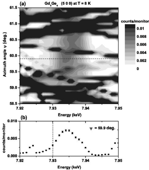
In this particular experiment the magnetic peak positions are forbidden for normal charge scattering, but can be strongly contaminated by multiple charge scattering. \( ^{15} \) However, the intensity of the multiple scattering is highly sensitive to both the incident beam energy and the azimuth angle \( \psi \) . For example, in Fig. 3(a) a contour map of intensity in dependence on energy and azimuth angle is shown at the position of the \( (5\ 0\ 0) \) reflection measured on the sample surface cut perpendicular to the a axis. The multiple scattering contribution at the resonant energy can be minimized through a judicious choice of azimuth angle as shown in Fig. 3(b), where the resonant scattering is well separated from the multiple scattering. We note that resonant scattering can arise from anomalous charge scattering in addition to magnetic scattering, \( ^{16} \) which will be discussed later.

FIG. 3. (a) Contour map of the intensity as a function of energy and azimuth angle \( \psi \) at the \( (5\ 0\ 0) \) position and T=8 K. Discontinuities in the bands of multiple scattering across the energy range are artifacts of the scanning process and (b) single energy scan at the azimuth angle \( \psi=59.9^{\circ} \) , which is depicted as a horizontal dashed line in (a). In (b), the vertical dashed line represents the position of the Gd \( L_{II} \) absorption edge.
III. RESULTS AND DISCUSSION
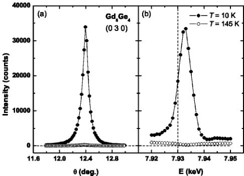
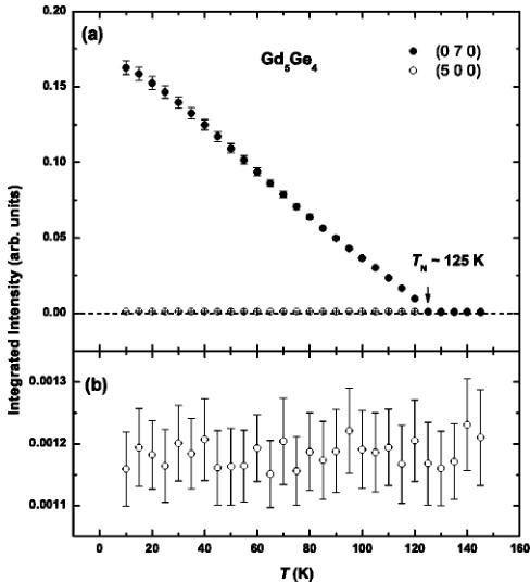
With the sample at low temperature and oriented so that the b-c orthorhombic axes were coincident with the scattering plane, a strong magnetic reflection was found at the nominally forbidden \( (0\ 3\ 0) \) charge reflection position as illustrated in Fig. 4(a). The full-width-half-maximum of the magnetic peak measured in \( \theta \) scans (rocking curves) was \( 0.1^{\circ} \) , the same as that from charge scattering. In order to confirm that the scattered intensity does indeed arise from resonant magnetic scattering, energy scans through the Gd \( L_{II} \) absorption edge were performed above and below the Néel temperature [see Fig. 4(b)]. At T=145 K, only charge scattering, arising from the tails of multiple scattering peaks, was observed. At low temperature, however, there is clear evidence of strong resonant scattering at the \( (0\ 3\ 0) \) magnetic peak position. Figure 5(a) displays the temperature dependence of the integrated intensity of the \( (0\ 7\ 0) \) magnetic peak. A Lorentzian peak shape was used to fit \( \theta \) scans through the reciprocal lattice points to obtain the integrated intensities. The intensity decreases smoothly to zero as temperature increases up to T=125 K. Magnetic reflections were found only at reciprocal lattice points \( (0\ k\ 0) \) , where k is odd. Therefore, the magnetic unit cell is the same as the crystallographic unit cell.
Having identified the location of the magnetic peaks and, therefore, the magnetic unit cell, we now turn to the deter-

FIG. 4. (a) \( \theta \) scan through the \( (0\ 3\ 0) \) magnetic peak at 10 K (filled circles) and 145 K (open circles) and (b) energy scans at 10 K (filled circles) and 145 K (open circles) through the magnetic peak. The data were measured at an azimuth angle of \( \psi=30^{\circ} \) using aluminum attenuator with 0.41 transmission. The dashed line represents the position of the Gd \( L_{II} \) absorption edge.
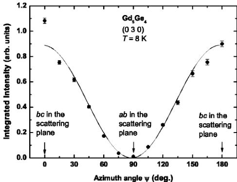
mination of the magnetic moment direction in the antiferromagnetic structure. This was accomplished by azimuth scans through the \( (0\ k\ 0) \) reflections. The \( (0\ 3\ 0) \) azimuth scan at T=8 K is shown in Fig. 6. The integrated intensities of the magnetic peak are normalized by the intensity of the \( (0\ 4\ 0) \) charge peak (at the same azimuth angle) to reduce systematic

FIG. 5. (a) Integrated intensity of the \( (0\ 7\ 0) \) magnetic peak measured upon heating the sample, at an azimuth angle of \( \psi=30^{\circ} \) , using an aluminum attenuator with 0.41 transmission. (b) Integrated intensity of the \( (5\ 0\ 0) \) resonant peak measured during heating at an azimuth angle of \( \psi=60^{\circ} \) without attenuator.

FIG. 6. The integrated intensity of the \( (0\ 3\ 0) \) magnetic peak normalized by the \( (0\ 4\ 0) \) charge peak at T=8 K. The solid curve represents the variation expected for magnetic moments along the c axis.
errors. At an azimuth angle \( \psi=90^{\circ} \) , where the a-b plane is coincident with the scattering plane, the integrated intensity is close to zero. We note that the intensity at \( \psi=90^{\circ} \) is close to zero over the entire temperature range investigated in this experiment (from 8 K to 140 K). This indicates that there is no contribution to the scattering at this reflection from an a or b component of the magnetic moment. Two maxima are found at azimuth values of \( \psi=0^{\circ} \) and \( 180^{\circ} \) where the b-c plane is coincident with the scattering plane. Therefore, only the c component contributes to the magnetic resonant scattering at this reflection.
The solid line in Fig. 6 represents the expected dependence, \( I=A\sin^{2}(\psi-\psi_{c}) \) , for the integrated intensity with \( \psi_{c}=(88.1\pm1.8)^{\circ} \) . The small deviation of \( \psi_{c} \) from \( 90^{\circ} \) results from a slight misalignment of the sample. The intensity at \( \psi=0^{\circ} \) deviates from the calculated curve because of particularly strong contributions from multiple scattering. Figure 6 indicates that either there is no magnetic moment component along a or b, or the intensity of the \( (0\ 3\ 0) \) magnetic peak is not sensitive to either the a or the b magnetic moment components due to cancelations arising from the symmetry of the magnetic order.
In order to determine the sensitivity of the magnetic reflections to different spatial components of the magnetic moment, we must look into the details of the possible magnetic space groups. For the \( Sm_{5}Ge_{4} \) -type structure with the crystallographic space group Pnma, eight magnetic space groups are possible, \( ^{17,18} \) and are listed in Table I. Each magnetic space group yields relations among the components of the magnetic moments along the three crystallographic axes described by modes. These modes represent the sign sequence of the moment components of each ion, in each site, along a particular direction.
In Table II the magnetic modes for the 4c and 8d Wyckoff sites are listed along with the corresponding structure factors for magnetic diffraction. From here, we see that only one mode, A, for the 4c site and two modes, R and \( A_{B} \) , for the 8d
TABLE I. The magnetic modes of the 4c and 8d Wyckoff sites for the eight possible magnetic space groups of the crystallographic space group Pnma associated with a magnetic unit cell that is the same as the crystallographic unit cell (based on Ref. 17 with a modified sequence of the atomic positions according to Ref. 18). The modes \( (A, C, F, G \) for a 4c site, \( A_{B}, C_{B}, F_{B}, G_{B}, L, P, Q, R \) for an 8d site) are characterized by the sign sequence for the magnetic moment components along the three crystallographic axes.
| Position | Pn'ma | Pnm'a | Pnma' | Pn'm'a | Pnm'a' | Pn'm'a' | Pn'm''a' | Pnma | |||||||||||||||||||||||
| a | b | c | a | b | c | a | b | c | b | c | a | b | c | a | b | c | a | b | c | a | b | c | a | b | c | ||||||
| i | 4c | G | G | A | A | C | F | F | C | F | A | G | C | ||||||||||||||||||
| 1 | x | 1/4 | z | + | + | + | + | + | + | + | - | + | + | + | |||||||||||||||||
| 2 | 1/2-x | 3/4 | 1/2+z | + | + | - | - | - | + | - | + | - | - | + | |||||||||||||||||
| 3 | -x | 3/4 | -z | - | - | - | - | + | + | + | - | + | - | - | + | ||||||||||||||||
| 4 | 1/2+x | 1/4 | 1/2-z | - | - | + | + | - | + | + | - | + | + | - | |||||||||||||||||
| i | 8d | P | L | Q | L | P | R | Q | R | P | G_{B} | C_{B} | F_{B} | F_{B} | A_{B} | G_{B} | A_{B} | F_{B} | C_{B} | R | Q | L | C_{B} | G_{B} | A_{B} | ||||||
| 1 | x | y | z | + | + | + | + | + | + | + | + | + | + | + | + | + | + + | + | + | + | + | + | + | + | + | + | + | ||||
| 2 | 1/2-x | -y | 1/2+z | + | + | - | + | + | - | - | - | - | + | + | + | + | - | + | + | - | - | - | - | - | + | + | |||||
| 3 | -x | 1/2+y | -z | + | - | + | - | + | - | + | + | + | - | + | + | - | + | + | - | + | - | + | - | - | + | + | |||||
| 4 | 1/2+x | 1/2-y | 1/2-z | + | - | - | - | + | + | - | + | + | + | + | + | - | - | + | + | + | - | + | - | + | + | ||||||
| 5 | -x | -y | -z | - | - | - | - | - | - | - | + | + | + | + | - | + | + + | + | + | + + | + | - | - | - | + | + | |||||
| 6 | 1/2+x | y | 1/2-z | - | - | + | - | + | + | - | + | - | + + | + | + | + | - | + | + | + | + | - | - | - | + | + + | |||||
| 7 | x | 1/2-y | z | - | + | - | + | - | + | - | - | + | + | - | + | + + + | + | + | - | + | + | - + | + | - | + | + | |||||
| 8 | 1/2-x | 1/2+y | 1/2+z | - | + | + | + | - | - | - | + | - | + | + | + | - | + | + | - | + | + | + | + | - | + | + | + | - | - | + | - |
 p1_0.jpg
 p2_0.jpg
 p2_1.jpg
 p3_0.jpg
 p3_1.jpg
 p3_2.jpg
| |||||||||||||||||||||||||||||||