| Parent Space Group | P-3m1 (#164) |
|---|---|
| Magnetic Space Group | C2'/m' (#12.62) |
| Magnetic Point Group | 2'/m' (5.5.16) |
| Lattice Parameters | 24.30000 24.30000 6.76000 90.00 90.00 120.00 |
|---|---|
| DOI | 10.1016/0921-4526(89)90661-3 |
| Reference | A. Wiedenmann, L. Regnault, P. Burlet, J. Rossat-Mignod, O. Kounde and D. Billerey, Physica B: Condensed Matter (1989) 156-157 305-307. |
| Label | Element | Mx | My | Mz | |M| |
|---|---|---|---|---|---|
| Fe1_1 | Fe | 0.0 | 0.0 | -1. | 1.00 |
| Fe1_2 | Fe | 0.0 | 0.0 | 1. | 1.00 |
| Fe1_3 | Fe | 0.0 | 0.0 | 1. | 1.00 |
| Fe1_4 | Fe | 0.0 | 0.0 | 1. | 1.00 |
| Fe1_5 | Fe | 0.0 | 0.0 | -1. | 1.00 |
Title
MAGNETIC PHASE DIAGRAM OF FeI_{2}
Authors
A. WIEDENMANN¹, L.P. REGNAULT², P. BURLET², J. ROSSAT-MIGNOD², O. KOUNDE³ and D. BILLEREY³ ¹ Hahn-Meitner-Institut, Glienicker Str. 100, D-1000 Berlin 39, Fed. Rep. Germany ² CEN6 – DRF/MDN, 85X, F-38041 Grenoble Cedex, France ³ Université de Nancy, F-54037 Nancy Cedex, France
Materials Studied
FeI_{2}
Key Information
- Crystal structure / space group: Hexagonal layered structure, space group P3ml.
- Magnetic ordering type and temperature:
- Paramagnetic (P) phase.
- Commensurate (C) phase in zero field.
- Four ferrimagnetic phases: F1, F2, F3, F4.
- Moments are aligned along the c-axis in all phases.
- Néel temperature (T_N): 9.3 K (in zero field).
- Tricritical point (T_c1): 3.8 K (transition to F1).
- Tricritical temperature (T_c2): 2.9 K (transition to F2).
- F1 and F2 are multi-k structures.
- F4 is a single-k structure.
- F3 is an "amorphous-like" phase with incomplete long-range ordering.
- Propagation vector(s):
- Commensurate (C) phase: k = [1/4 0 1/4]
- Ferrimagnetic F1 phase: k₁ = [1/6 1/6 0], k₂ = [1/3 -1/6 0], k₃ = [1/6 -1/3 0] (and second and sixth harmonics).
- Ferrimagnetic F2 phase: k₁ = [1/5 1/5 0], k₂ = [2/5 1/5 0], k₃ = [1/5 2/5 0], k₀ = 0 (and k'=[1/5 0 0], k''=[0 1/5 0], k'''=[1/5 1/5 0] and their second harmonics, though weak).
- Ferrimagnetic F4 phase: k (F4) = [1/5 2/5 0] (same wave vectors as F2).
- Magnetic moments:
- Zero-field moment (m₀): 4.1 μ_B.
- Net magnetization of F1 phase (σ(F1)): m₀/3.
- Net magnetization of F2 phase (σ(F2)): 0.44 m₀.
- Net magnetization of F3 phase (σ(F3)): 0.5 m₀.
- Net magnetization of F4 phase (σ(F4)): 0.6 m₀.
- Lattice parameters: a = 4.05 Å, c = 6.75 Å.
- Other critical measured values:
- Exchange integrals:
- J₁/k = (1.65 ± 0.3) K
- J₂/k = -(0.29 ± 0.01) K
- J₃/k = -(1.55 ± 0.04) K
- J₀'/k = (0.47 ± 0.08) K
- J₁'/k = -(1.36 ± 0.03) K
- Paramagnetic Curie temperature (θ_p): 23.0 K (experimental), 20.6 K ≤ θ_p ≤ 23.7 K (calculated).
- Exchange integrals:
Synthesis Method
A single crystal of FeI₂ was grown by a Bridgman technique.
Abstract
Neutron diffraction experiments and magnetization measurements have revealed first order transitions between the paramagnetic (P), a commensurate (C), and four ferrimagnetic phases F1 to F4, moments being aligned along the c-axis. F1 and F2 are multi-k structures, F4 is a single-k structure and F3 is an “amorphous-like” phase. Five exchange integrals showing competing interactions are derived.
Main Content Summary
The study investigates the magnetic phase diagram of FeI₂, a ferrous halide crystallizing in a hexagonal layered structure (space group P3ml) with lattice parameters a=4.05 Å and c=6.75 Å. At a Néel temperature of 9.3 K, FeI₂ exhibits a commensurate magnetic structure in zero applied field, characterized by a wave vector k=[1/4 0 1/4]. This structure consists of ferromagnetic (101) layers stacked in an a++-- sequence, with Fe²⁺ moments of 4.1 μ_B aligned along the c-axis. The research utilized neutron scattering and magnetization measurements on a single crystal, oriented with its c-axis parallel to the external magnetic field, to map out the (H, T) phase diagram.
Magnetization isotherms below T_N reveal several first-order phase transitions, marked by distinct magnetization steps and hysteresis effects, leading to a complex H-T phase diagram. Beyond the paramagnetic (P) and zero-field commensurate (C) phases, four ferrimagnetic phases (F1, F2, F3, F4) were identified. The F1 phase, observed below a tricritical point of 3.8 K, is a multi-k structure involving three fundamental components and higher harmonics, resulting in an in-plane arrangement where blocks of four moments are antiparallel to the field, surrounded by parallel moments, yielding a net magnetization of m₀/3. The F2 phase, appearing below 2.9 K, is also a multi-k structure with a net magnetization of 0.44 m₀, characterized by a trigonal symmetry and a 5a x 5a unit cell. The F4 phase, with a net magnetization of 0.6 m₀, is a single-k structure corresponding to a ++++- stacking of ferromagnetic (110) planes. In contrast, the F3 phase, with 0.5 m₀ magnetization, shows only a broad magnetic peak, suggesting an "amorphous-like" state with local ordering but limited long-range correlation.
The observed magnetic phase diagram is attributed to significant frustration effects within the triangular lattice, arising from competing in-plane (J₁, J₂, J₃) and inter-plane (J₀', J₁', J₂') exchange interactions. By analyzing the energy of the various magnetic phases in an applied field and at critical transitions, a set of five exchange integrals was derived. These include J₁/k = (1.65 ± 0.3) K, J₂/k = -(0.29 ± 0.01) K, J₃/k = -(1.55 ± 0.04) K, J₀'/k = (0.47 ± 0.08) K, and J₁'/k = -(1.36 ± 0.03) K. The calculated paramagnetic Curie temperature (20.6 K ≤ θ_p ≤ 23.7 K) based on these integrals shows good agreement with the experimental value of 23.0 K, validating the derived exchange parameters.
Conclusion
In summary, we conclude that in FeI₂ the coupling between first nn inside the (001) plane is ferromagnetic and is of comparable magnitude to that between third nn on the (001) plane and between second nn on adjacent layers.
MAGNETIC PHASE DIAGRAM OF FeI_{2}
A. WIEDENMANN¹, L.P. REGNAULT², P. BURLET², J. ROSSAT-MIGNOD², O. KOUNDE³ and D. BILLEREY³
\( ^{1} \) Hahn-Meitner-Institut, Glienicker Str. 100, D-1000 Berlin 39, Fed. Rep. Germany
\( ^{2} \) CEN6 – DRF/MDN, 85X, F-38041 Grenoble Cedex, France
\( ^{3} \) Université de Nancy, F-54037 Nancy Cedex, France
Neutron diffraction experiments and magnetization measurements have revealed first order transitions between the paramagnetic (P), a commensurate (C), and four ferrimagnetic phases F1 to F4, moments being aligned along the c-axis. F1 and F2 are multi-k structures, F4 is a single-k structure and F3 is an “amorphous-like” phase. Five exchange integrals showing competing interactions are derived.
1. Introduction
FeI_{2} belongs to the ferrous halides which crystallize in a hexagonal layered structure of space group P3ml. The unit cell (a=4.05 Å, c=6.75 Å) contains one Fe^{2+} ion located on the trigonal axis at the origin (000) and two I^{-}-ions at the positions (1/3 2/3 z) and (2/3 1/3 z) with z\approx1/4. At the Néel temperature, T_{N}=9.3 K [1], a commensurate magnetic structure is built up in zero field [2]. The magnetic phase diagram (H, T) and the nature of the various intermediate magnetic phases were studied by means of neutron scattering and magnetization measurements [4]. A single crystal of FeI_{2} grown by a Bridgman technique was oriented with the c-axis parallel to the external field.
2. Results
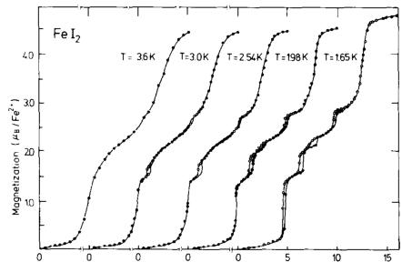
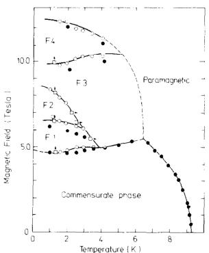
Magnetization isotherms \( M(H) \) below \( T_{N}=9.3 \) K exhibit several magnetization steps at the critical values \( H_{c_{i}} \) which (accompanied by hysteresis effects) are characteristic for first order phase transitions (fig. 1). The corresponding H-T phase diagram is shown in fig. 2. In zero applied field a commensurate magnetic ordering is defined by the wave vector \( k=[1/4\ 0\ 1/4] \) . It consists of a stacking of ferromagnetic (101) layers in \( a++-- \) sequence with moments \( (m_{0}=4.1\ \mu_{B}) \) aligned along the c-axis. At a

Fig. 1. Magnetization as a function of a magnetic field applied along the c-axis.
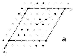
critical field \( H_{c_{1}} \) a first order transition to a ferrimagnetic phase F1 takes place for temperatures below the tricritical point \( T_{c_{1}} = 3.8 K \) . The F1 phase is a multi-k structure involving the three fundamental components with \( k_{1} = [1/6\ 1/6\ 0] \) , \( k_{2} = [1/3\ \overline{1/6}\ 0] \) and \( k_{3} = [1/6\ \overline{1/3}\ 0] \) and the second and sixth harmonics. Good agreement between observed and calculated intensities ( \( R = 6\% \) ) is found for the inplane ordering shown in fig. 3(a). It consists of blocks of four magnetic neighbour moments aligned along the c-axis and antiparallel to the applied field surrounded by parallel aligned moments, yielding a net magnetization \( \sigma(\mathrm{F1}) = m_{0}/3 \) . Nearest neighbouring moments in adjacent (001) layers arc aligned parallel to each other.

Fig. 2. Magnetic phase diagram of \( FeI_{2} \) determined from magnetization (circles) and neutron diffraction experiments (squares) (full circles: [3]).
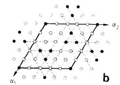
A transition to a second ferrimagnetic phase F2 occurs at \( H_{c_{2}} \) below a tricritical temperature \( T_{c_{2}} = 2.9 \, K \) . This phase has a net magnetization \( \sigma(\mathrm{F2}) = 0.44 m_{u} \) resulting from an in-plane moment arrangement reported in fig. 3(b), characterized by triangles and isolated “down” moments surrounded by “up” moments. This magnetic structure of a unit cell \( 5a \times 5a \) has a trigonal symmetry and hence has no k-domains.
Besides the observed commensurate wave vectors \( k_{1}=[1/5\ 1/5\ 0] \) , \( k_{2}=[2/5\ 1/5\ 0] \) , \( k_{3}=[1/5\ 2/5\ 0] \) and \( k_{0}=0 \) for this ordering, the amplitude of the Fourier components associated with the second harmonics 2k and with the wave vectors \( \boldsymbol{k}^{\prime}=[1/5\ 0\ 0] \) , \( \boldsymbol{k}^{\prime\prime}=[0\ 1/5\ 0] \) and \( \boldsymbol{k}^{\prime\prime\prime}=[1/5\ 1/5\ 0] \) and their second harmonics are non-zero, but they are too weak to be observed experimentally ( \( R=25\% \) ).
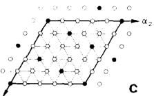
Another ferrimagnetic phase F4 exists above a critical field \( H_{c_{4}} \) with a net magnetization \( \sigma(\mathrm{F4}) = 0.6m_{0} \) with the same wave vectors as for phase F2. The ordering of the phase F4 corresponds to a single-k structure, i.e. a stacking of ferromagnetic (110) planes with a sequence \( ++ + + - \) (fig. 3(c)). However, a squaring up of the sine-wave modulation would give rise to a second order harmonic 2k which has not been observed experimentally.


Fig. 3. Arrangement of moments of Fe ions in the (001) plane parallel (open circles) and antiparallel (closed circles) to the external field. (a) Ferromagnetic multi-k structure phase F1. The unit cell is \( 6a \times 6a \times c \) (full line) and the elementary unit cell \( 2\sqrt{3}a \times 2\sqrt{3}a \times c \) , (dashed line). (b) Ferromagnetic multi-k structure F2. The magnetic unit cell is \( 5a \times 5a \times c \) . (c) Ferromagnetic single-k structure F4 defined by the wave vector k (F4) = \( [1/5\ 2/5\ 0] \) .
The magnetic moments in the F3 phase must be ordered since the net magnetization \( \sigma(\mathrm{F3}) = 0.5m_{u} \) is much lower than that expected for the paramagnetic state. The ordering is not long-range since no magnetic reflections but only a very broad peak was observed along the [110] direction. This type of incomplete long-range ordering is similar to that found in amorphous systems. A local ordering is present but the correlation length must be small due to the great variety of possible moment arrangements.
3. Discussion
The magnetic phase diagram of \( FeI_{2} \) results from important frustration effects present in the
triangular lattice due to the competition between various in-plane and inter-plane interactions. The most important in-plane couplings are the superexchange interactions via the iodide ions between first nearest neighbour (nn) \( Fe^{2+} \) ions \( (J_{1}) \) at \( d_{1}=4.05\ \AA \) second nn \( (J_{2}) \) at 7.01 Å, and third nn \( (J_{3}) \) at 8.1 Å. The couplings between adjacent layers \( J_{0}^{\prime} \) at \( d_{0}^{\prime}=6.75\ \AA \) , \( J_{1}^{\prime} \) at \( d_{1}^{\prime}=7.78\ \AA \) and \( J_{2}^{\prime} \) and \( d_{2}^{\prime}=9.73\ \AA \) are expected to be much weaker. The energy of the various ferrimagnetic phases in an applied field can be written as
\[ E_{i}(H)=E_{\mathrm{e x}}-\sigma_{\mathrm{f}}\cdot m_{0}\cdot H. \quad (1) \]
The exchange energy \( E_{ex} \) is calculated for the above determined structure F1, F2, F4, the commensurate and the paramagnetic phase according to
\[ E_{\mathrm{e x}}=-\sum_{i j}J_{i j}S_{i}^{2}\cdot S_{j}^{2} \quad (2) \]
\( (S_{i}^{2}=\pm1) \) . At the critical field \( H_{c} \) the energy of the corresponding phases must be equal i.e.
\[ E_{i}-E_{j}=(\sigma_{i}-\sigma_{j})m_{0}\cdot H_{c}. \quad (3) \]
Furthermore, the thermal energy at the Néel temperature \( T_{N} \) is equal to the ground state energy of the commensurate phase, i.e.
\[ k T_{\mathrm{N}}=\textstyle{\frac{2}{3}}S(S+1)(E_{\mathrm{c}}). \quad (4) \]
From eqs. (2) to (4) a set of five exchange integrals is derived. Using the observed values of \( H_{c_{i}} \) , \( T_{N}=9.3+0.2 \) K and \( m_{0}=(4.1\pm0.1)\mu_{\mathrm{B}} \) , the following exchange integrals are obtained: \( J_{1}/k=(1.65\pm0.3) \) K, \( J_{2}/k=-(0.29\pm0.01) \) K, \( J_{3}/k=-(1.55\pm0.04) \) K, \( J_{0}^{\prime}/k=(0.47\pm0.08) \) K and \( J_{1}^{\prime}/k=-(1.36\pm0.03) \) K. With this set a paramagnetic Curie temperature
\[ k\theta_{\mathrm{p}}=\textstyle{\frac{2}{3}}S(S+1)E_{\mathrm{p}}, \]
20.6 K ≤ θp ≤ 23.7 K, is expected in good agreement with the experimental value of θp = 23.0 K.
In summary, we conclude that in \( FeI_{2} \) the coupling between first nn inside the (001) plane is ferromagnetic and is of comparable magnitude to that between third nn on the (001) plane and between second nn on adjacent layers.
References
[1] J. Gelard, A.R. Fert, P. Meriel and Y. Allain, Solid State Commun. 14 (1974) 187.
[2] A.R. Fert, J. Gelard and P. Carrara, Solid State Commun. 13 (1973) 1219.
[3] D. Petitgrand, B Hennion and C. Escribe, J. Physique Lett. 41 (1980) L135.
[4] A. Wiedenmann, L.P. Regnault, P. Burlet, J. Rossat-Mignod, O. Koundé and D. Billerey, J. Magn. Magn. Mat. 74 (1988) 7.
 p1_0.jpg
 p2_0.jpg
 p2_1.jpg
 p2_2.jpg
 p2_3.jpg