| Transition Temperature | 100 K |
|---|---|
| Experiment Temperature | 2 K |
| Propagation Vector | k1 (0, 0, 0) |
| Parent Space Group | C2/c (#15) |
| Magnetic Space Group | C2'/c' (#15.89) |
| Magnetic Point Group | 2'/m' (5.5.16) |
| Lattice Parameters | 7.36500 7.09000 7.36800 90.00 119.77 90.00 |
|---|---|
| DOI | 10.1021/cm200465u |
| Reference | B.C. Melot, G. Rousse, J.-N. Chotard, M. Ati, J. Rodriguez-Carvajal, M.C. Kemei and J.-M. Tarascon, Chemistry of Materials (2011) 23 2922-2930. |
| Label | Element | Mx | My | Mz | |M| |
|---|---|---|---|---|---|
| Fe1 | Fe | 0.0 | 4.32 | 0.0 | 4.32 |
Magnetic Structure and Properties of the Li-Ion Battery Materials FeSO_{4}F and LiFeSO_{4}F
B. C. Melot, \( ^{\dagger} \) G. Rousse, \( ^{*\ddagger} \) J.-N. Chotard, \( ^{\dagger} \) M. Ati, \( ^{\dagger} \) J. Rodríguez-Carvajal, \( ^{\S} \) M. C. Kemei, \( ^{\perp} \) and J.-M. Tarascon \( ^{*\dagger} \) \( ^{\dagger} \) Laboratoire de Réactivité et Chimie des Solides, CNRS UMR 6007, Université de Picardie Jules Verne, 33 rue Saint-Leu, 80039 Amiens – France
\( ^{\dagger} \) Institut de Minéralogie et de Physique des Milieux Condensés (IMPMC), UMR 7590 CNRS, Université Pierre et Marie Curie (UPMC), Case courrier 115, 4 Place Jussieu, 75252 Paris Cedex 05, France
\( ^{\S} \) Institut Laue-Langevin (ILL) Diffraction group, 6, rue Jules Horowitz BP 156 - 38042 Grenoble Cedex 9, France
\( ^{\perp} \) Materials Department and Materials Research Laboratory, University of California, Santa Barbara, California 93106, United States
ABSTRACT: Using magnetic susceptibility and low-temperature neutron diffraction experiments we present a thorough characterization of the magnetic properties of \( LiFeSO_{4}F \) and \( FeSO_{4}F \) . Temperature dependent magnetic susceptibility measurements show a transition to long-range antiferromagnetic order at 100 K in \( FeSO_{4}F \) whereas the ordering temperature in \( LiFeSO_{4}F \) is 25 K. We attribute the decreased ordering temperature to a structural change which decreases the strength of the magnetic interactions along the length of the chains and to the difference of super-super-exchange interactions between \( Fe^{2+} \) and \( Fe^{3+} \) ions. Powder neutron diffraction experiments were used to determine the magnetic structures of both compounds, which are discussed in terms of exchange interactions and the anisotropy of \( Fe^{2+} \) . The

iron magnetic moments are antiparallel within the chains, whereas the coupling between the chains is different in the lithiated compound compared to the delithiated one, resulting in different spin arrangements.
KEYWORDS: structure-magnetism, powder neutron diffraction, battery, fluorosulfates
■ INTRODUCTION
Lately there has been a surge of research on polyanionic materials such as sulfates and phosphates for applications in Li-ion batteries. \( ^{1} \) This interest stems from the high energy density and good operating voltages that have been demonstrated in materials like \( LiFePO_{4} \) . \( ^{2} \) More recently, compounds which incorporate stronger electron-withdrawing anions, such as fluorine, have been investigated because of their promise of higher operating potentials. One exciting realization of this idea is found in \( LiFeSO_{4}F \) , which shows a 150 mV enhancement of the cell voltage over \( LiFePO_{4} \) . \( ^{3} \)
Although these fluorinated compounds clearly show all the characteristics required for good cathode materials, their low thermodynamic stability when compared to their nonfluorinated counterparts requires that new avenues for materials preparation be developed. A review of several new synthetic approaches has been presented elsewhere, \( ^{4,5} \) but the dominant theme of these methods is to exploit kinetic control over reactions such that new phases can be stabilized in moderate-temperature reaction conditions. In the case of \( LiFeSO_{4}F \) , the dehydration of \( FeSO_{4}\cdot H_{2}O \) is done in such a way that LiF is given sufficient time to incorporate into the structure and form the target phase. Tarascon and co-workers have done extensive work investigating the role that hydrophobic ionic liquids can play in slowing down the removal of water and in developing novel synthetic ways for this material bearing a much lower cost. The first is based on a solid-state process, \( ^{6} \) while the other utilizes a polymer media. \( ^{7} \) In parallel, other groups such as Nazar et al. have explored the use of hydrophilic solvents like tetraethylene glycol to speed up the penetration of LiF into the parent compound. \( ^{8} \)
Although extensive studies have been reported on the electrochemical properties of these new favorite fluorosulfate phases, very little work has been done to characterize their magnetic properties. In this work, we report on the nature of the magnetic interactions in \( FeSO_{4}F \) and \( LiFeSO_{4}F \) . Both compounds are of interest from the point-of-view of magnetism due to the presence of one-dimensional chains of octahedrally coordinated Fe. This type of chain architecture is known to demonstrate a wide variety of interesting physics including magnetodielectric coupling and noncollinear magnetic structures as found in \( CoSeO_{9}^{4} \) and \( LiCu_{2}O_{2}^{10} \) respectively. Using temperature-dependent magnetic susceptibility measurements, we find a significant change in the ordering temperature from 100 K in \( FeSO_{4}F \) to 25 K in \( LiFeSO_{4}F \) . We discuss how the presence of Li alters the crystal structure and correlates these changes to the diminished ordering temperature. We also use low-temperature powder neutron diffraction to propose a model for the magnetic structure in both phases and discuss the magnetic
structure in terms of the anisotropy of \( Fe^{2+} \) . Finally, we perform an analysis of the super and supersuperexchange interactions and discuss the relative strengths required to obtain the observed magnetic structures as the ground state.
■ EXPERIMENTAL SECTION
The title compounds were prepared following previously reported procedures. \( ^{3} \) Powders of \( LiFeSO_{4}F \) were prepared by a two-step process. First, commercially available \( FeSO_{4}F\cdot7H_{2}O \) was dehydrated in a primary vacuum at \( 200^{\circ}C \) to produce the monohydrate. The obtained \( FeSO_{4}\cdotH_{2}O \) was reacted in a Teflon-lined steel bomb with LiF in an ionic-liquid medium at \( 300^{\circ}C \) for 5 h. Once cooled, the powder and ionic liquid were separated by centrifugation. The recovered powder, which was gray to sandy-gray in color, was washed with dichloromethane and oven-dried under vacuum at \( 60^{\circ}C \) . \( FeSO_{4}F \) was obtained as an off-white powder via chemical oxidation of the as-prepared \( LiFeSO_{4}F \) using \( NO_{2}BF_{4} \) in acetonitrile.
Sample purity was analyzed by laboratory powder X-ray diffraction (XRD), using a Bruker D8 diffractometer with Co Kα radiation ( \( \lambda_{1}=1.7892 \) Å, \( \lambda_{2}=1.7932 \) Å) equipped with a Vantec detector. Neutron diffraction data were collected on the D2B and D20 powder diffractometers at the Institut Laue-Langevin (ILL), France using a wavelength of 1.594 Å and 2.420 Å, respectively. The D2B diffractometer has a very high resolution and was therefore used to precisely refine the nuclear structure of \( LiFeSO_{4}F \) at room temperature. The high intensity neutron powder diffractometer D20, which presents a good resolution at low angle, was used to determine the magnetic structure of the both title compounds. The temperature dependence of the dc magnetization was measured on well-ground powder samples using a Quantum Design magnetic property measurement system (MPMS) SXL superconducting quantum interference device magnetometer (SQUID). The FullProf program \( ^{11} \) was used for nuclear and magnetic structure refinements using the Rietveld method \( ^{12} \) and for distance and bond valence sum calculations. \( ^{13} \)
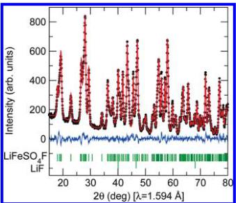
Crystal Structure of \( LiFeSO_{4}F \) and \( FeSO_{4}F \) . The crystal structure of \( LiFeSO_{4}F \) was refined from powder neutron diffraction on D2B at room temperature, the results of which are shown in Figure 1. Traces of LiF are visible in the neutron diffraction patterns so LiF was included as a secondary phase in the refinement. A summary of the crystallographic parameters is given in Table 1. The delithiated compound \( FeSO_{4}F \) crystallizes in the monoclinic space group \( C2/c,^{8} \) which is closely related to the triclinic cell of \( LiFeSO_{4}F \) , as one can describe \( FeSO_{4}F \) either in the monoclinic cell, or in the same triclinic cell as \( LiFeSO_{4}F \) , for make the comparison between both structures easier.
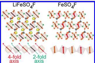
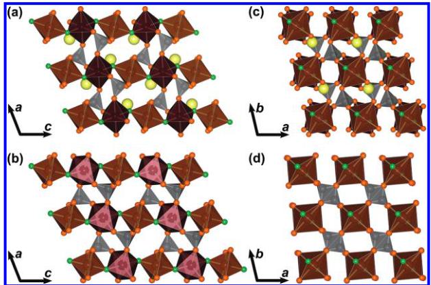
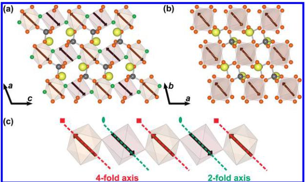
The crystal structures of \( LiFeSO_{4}F \) and \( FeSO_{4}F^{-} \) are illustrated in Figure 2a/c and b/d, respectively. Both phases consist of \( FeO_{4}F_{2} \) octahedra that are bound together at their corners through F atoms that are oriented in a trans configuration with respect to each other, giving rise to buckled chains. All of the oxygen atoms in the structure are bound within \( SO_{4} \) tetrahedra which connect the chains via shared corners on the \( FeO_{4}F_{2} \) octahedra. These chains, which are along the c axis of the triclinic cell, are clearly visible in Figure 2a for \( LiFeSO_{4}F \) and Figure 2b for \( FeSO_{4}F \) . We can also illustrate this structure as having a perovskite topology for the Fe ions with additional \( SO_{4} \) polyedra connecting chains. Another way to describe the structure is represented in panels c and d in Figure 2, which consists of a stacking of two kind of layers that are alternately stacked along the direction of the chains. Within an individual layer, the iron atoms are connected through two \( SO_{4} \) tetrahedra, and the direction of this connection changes from one plane to another, creating a 3D polyanionic network. It should be noted that there is only one F site in both structures and that the Fe—F—Fe bond angle dictates the degree of buckling along the chains.
Upon the insertion of lithium atoms, the symmetry drops from C2/c to P1. This implies that the single iron atom in the monoclinic cell splits into two independent Wyckoff sites (1a and 1b) and that the two oxygen

Figure 1. Portion of the refined neutron diffraction pattern at room temperature for \( LiFeSO_{4}F \) collected on D2B ( \( \lambda = 1.594 \AA \) ) at the ILL. The positions of the Bragg reflections are shown as vertical bars. The difference (obs - calcd) pattern is displayed in blue.
Table 1. Crystallographic Data of LiFeSO_{4}F Resulting from Refinements of the Structure against the Data Collected on the High-Resolution Powder Neutron Diffractometer D2B Obtained at Room Temperature, R_{Bragg} = 2.72%
| space group | P \( \bar{1} \) | ||
| a ( \( \textup{\AA} \) ) | 5.18003(7) | ||
| b ( \( \textup{\AA} \) ) | 5.49165(6) | ||
| c ( \( \textup{\AA} \) ) | 7.22890(9) | ||
| \( \alpha \) (deg) | 106.4864(9) | ||
| \( \beta \) (deg) | 107.186(9) | ||
| \( \gamma \) (deg) | 97.9098(9) | ||
| V ( \( \textup{\AA}^{3} \) ) | 182.793(4) | ||
| atom | Wyckoff | x | y |
| Li | 2i | 0.270(1) | 0.634(2) |
| Fe1 | 1b | 0 | 0 |
| Fe2 | 1a | 0 | 0 |
| S | 2i | 0.3244(9) | 0.6381(9) |
| O1 | 2i | 0.5976(5) | 0.7469(5) |
| O2 | 2i | 0.1063(5) | 0.6407(5) |
| O3 | 2i | 0.3198(6) | 0.3564(5) |
| O4 | 2i | 0.2790(5) | 0.7708(5) |
| F | 2i | 0.1259(5) | 0.9144(5) |
| \( ^{a} \) Anisotropic \( \beta \) ( \( \times \) 10 \( ^{4} \) ): \( \beta_{11} \) = 518(75), \( \beta_{22} \) = 180(45), \( \beta_{33} \) = 534(54), \( \beta_{12} \) = 341(46), \( \beta_{13} \) = 289(45), \( \beta_{23} \) = 237(38) | |||
atoms of the delithiated phase generate four sites in the triclinic \( LiFeSO_{4}F \) which are all located on the 2i Wyckoff position. Contrary to previous reports based on X-ray powder diffraction which claim that lithium ions in \( LiFeSO_{4}F \) partially occupy two different crystallographic sites, \( ^{8} \) we find that neutron diffraction refinements allow for a more accurate determination of the lithium position in the channels. Our results indicate that the lithium ions sit on only one position, which is located between the two sites previously suggested and is fully occupied as shown in Table 1. Refinement of the anisotropic atomic displacement parameter for lithium also supports the notion that the lithium ions are mobile within the tunnels between the chains as supported by the performance of the compound as a positive electrode material in Li-ion batteries. \( ^{3} \)
The Li atoms are positioned within the channels between the chains and are effectively coordinated by one fluorine and two oxygen atoms to

Figure 2. Illustration of the crystal structure of \( (a, c) \) LiFeSO \( _{4} \) F and \( (b, d) \) FeSO \( _{4} \) F. Fe site 1 and Fe site 2 are shown in red and brown, respectively. S is gray, O is orange, and F is green. The structure is composed of corner-sharing octahedra of two unique Fe sites which share corners through F atoms sitting trans with respect to each other along the length of the chains. Note that FeSO \( _{4} \) F is illustrated here in the P \( \overline{T} \) unit cell rather than C2/c in order to provide a more direct comparison with LiFeSO \( _{4} \) F.
form a trigonal planar coordination. This is reflected in the M-F-M bond angle, which increases from \( 129^{\circ} \) in \( LiFeSO_{4}F \) to \( 145^{\circ} \) in \( FeSO_{4}F \) . It should be noted that this structural change is accomplished via a rotation of the Fe1 octahedra about the F-M-F axis such that it falls into registry with the rotation of the Fe2 octahedra as illustrated in Figure 2c, d. A bond valence analysis for both \( LiFeSO_{4}F \) and \( FeSO_{4}F \) phases was performed and gave valence sum values of 2.04 (1) and 2.06 (1) for each Fe site in \( LiFeSO_{4}F \) and 3.05(3) for \( FeSO_{4}F \) , in very good agreement with what is expected for \( Fe^{2+} \) in \( LiFeSO_{4}F \) and \( Fe^{3+} \) in \( FeSO_{4}F \) .
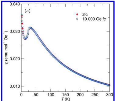
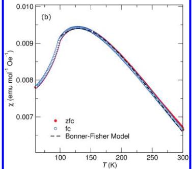
Magnetic Properties of \( LiFeSO_{4}F \) and \( FeSO_{4}F \) . The temperature dependence of the magnetic susceptibility for the title compounds is shown in panels a and b in Figure 3. In a field of 10 kOe, both compounds show cusps indicative of the onset of antiferromagnetic ordering at 100 and 25 K for \( FeSO_{4}F \) and \( LiFeSO_{4}F \) , respectively. Below 20 K, both samples show sharp upturns characteristic of a paramagnetic contribution which likely comes from imperfections in the crystal structure as has been found previously in other magnetic systems with reduced dimensionality. \( ^{14} \) It should also be noted that the zero-field-cooled (zfc) and field-cooled (fc) traces do not perfectly overlap in the region of 30–50K for the data collected from \( FeSO_{4}F \) . We attribute this feature to some partially lithiated phase (ie: \( Li_{x}FeSO_{4}F \) ) which is the result of an incomplete extraction of Li during the sample preparation.
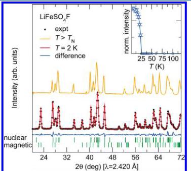
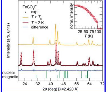
Neutron diffraction patterns were collected between 2 and 50 K for \( LiFeSO_{4}F \) and between 2 and 125 K for \( FeSO_{4}F \) on the high intensity powder neutron diffractometer D20 at the Institut Laue-Langevin, which is especially well adapted for magnetic structure determination, using a wavelength of 2.420 Å. Several extra peaks that correspond to the onset of long-range magnetic ordering evolve upon cooling below the respective ordering temperature as seen in Figure 4. The intensity of the strongest magnetic reflection for both phases is plotted as a function of temperature in the insets of Figure 4 with the observed ordering temperature, in good agreement with the temperature-dependent susceptibility data. We remark that the Néel temperature is much higher for \( FeSO_{4}F \) (100K) than for \( LiFeSO_{4}F \) (25K).
Magnetic Structure of \( FeSO_{4}F \) . The magnetic peaks appearing in the powder neutron diffraction patterns below 100K can be indexed in the same cell as the nuclear structure which gives a propagation vector \( \mathbf{k}=(0\ 0\ 0) \) with the C lattice centering conserved. A symmetry analysis


Figure 3. Temperature-dependent magnetic susceptibility of (a) \( LiFeSO_{4}F \) and (b) \( FeSO_{4}F \) . The transition temperature increases from 25 to 100 K with the removal of Li. Note that \( FeSO_{4}F \) demonstrates a much broader maximum reminiscent of systems with one-dimensional magnetic ordering and fits well to the Bonner–Fisher model of a classical chain of spins as denoted by the dashed line.
was performed using Bertaut's method \( ^{15} \) as implemented in the program BASIREPS \( ^{16} \) to determine all of the possible spin configurations which


Figure 4. Observed (black dots) versus calculated (red line) powder neutron diffraction patterns of \( LiFeSO_{4}F \) (upper panel) and \( FeSO_{4}F \) (lower panel) collected at 2 K on D20 with \( \lambda = 2.420 \AA \) . The difference pattern (blue line) is displayed at the bottom of the figure. The patterns recorded above the magnetic transition are displayed (orange line) for comparison. The insets show the evolution of intensity of the \( (-^{1}/_{2}-^{1}/_{2}1) \) magnetic peak for \( LiFeSO_{4}F \) and of the (001) magnetic peak of \( FeSO_{4}F \) with temperature. Note that the ordering temperatures are in good agreement with the temperature-dependent susceptibility.
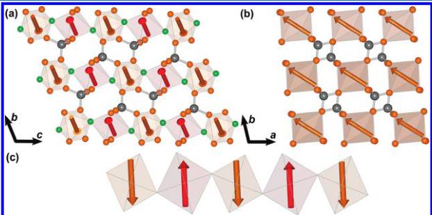
are compatible with the crystal symmetry of \( FeSO_{4}F \) . \( FeSO_{4}F \) has monoclinic symmetry, with only one crystallographic site for the iron atoms on the 4d Wyckoff site \( \left(\frac{1}{4}, \frac{1}{4}, \frac{1}{2}\right) \) . With the C2/c space group and \( \mathbf{k} = (0 \ 0 \ 0) \) , there are two one-dimensional irreducible representations associated with the 4d site: \( \Gamma_{mag} = 3 \ \Gamma_{1} \oplus 3 \ \Gamma_{3} \) . These representations are built with basis vectors that correspond to moments oriented along the a, b or c unit cell directions. The basis vectors of the \( \Gamma_{1} \) representation correspond to a coupling of the two iron atoms within a primitive cell, located at \( \left(\frac{1}{4}, \frac{1}{4}, \left(\frac{1}{2}\right)\right) \) and \( \left(-\frac{1}{4}, \frac{1}{4}, 0\right) \) in the conventional cell, being parallel along b and antiparallel along a and c. The magnetic moments are of the form \( (u, v, w) \) and \( (-u, v, -w) \) , respectively. The basis vectors of the \( \Gamma_{3} \) representation correspond to the opposite coupling: \( (u, v, w) \) and \( (u, -v, w) \) . The best agreement with the observed magnetic reflections is obtained using \( \Gamma_{3} \) where the moments orient along b with negligible x-z components. The refined value of the magnetic moment is \( 4.32 \mu_{B} \) in good agreement with what is expected for \( Fe^{3+} \) ions. The magnitude and orientation of the magnetic moments are listed in Table 2 and the magnetic structure is illustrated in Figure 5. The moments are antiparallel along the length of the corner-sharing \( FeO_{4}F_{2} \) chains and aligned parallel between the chains.
Table 2. Nuclear and Magnetic Structure of FeSO_{4}F Determined from Refinement of the Structure against Powder Neutron Diffraction on D20 at 2 K^{a}
| atom | Wyckoff | x | y | z |
| S | 4e | 0 | 0.647 (1) | \( ^{1}/_{4} \) |
| Fe | 4d | \( ^{1}/_{4} \) | \( ^{1}/_{4} \) | \( ^{1}/_{2} \) |
| F | 4e | 0 | 0.167 (1) | \( ^{1}/_{4} \) |
| O(1) | 8f | 0.338 (1) | 0.016 (1) | 0.084 (1) |
| O(2) | 8f | 0.412 (1) | 0.264 (1) | 0.346 (1) |
| atom | \( M_{a}^{b} \) | \( M_{b}^{b} \) | \( M_{c}^{b} \) | \( \rho \) (deg) |
| Fe ( \( ^{1}/_{4} \) , \( ^{1}/_{4} \) , \( ^{1}/_{2} \) ) | 0 | 4.32 (3) | 0 | 4.32 (3) |
| Fe ( \( ^{−1}/_{4} \) , \( ^{1}/_{4} \) , 0) | 0 | 4.32 (3) | 0 | 4.32 |
| Fe ( \( ^{3}/_{4} \) , \( ^{3}/_{4} \) , \( ^{1}/_{2} \) ) | 0.32 (3) | 0 | 4.32 (3) | 90 |
| Fe ( \( ^{1}/_{4} \) , \( ^{3}/_{4} \) , 0) | 0 | 4.32 (3.2) | 0 | 4.32 |
\( ^{a} \) space group C2/c, a = 7.365(1) \( \AA \) , b = 7.090(1) \( \AA \) , c = 7.368(1) \( \AA \) , \( \alpha = 90^{\circ} \) , \( \beta = 119.768(1)^{\circ} \) , \( \gamma = 90^{\circ} \) V = 334.01(2) \( \AA^{3} \) , \( R_{Bragg} = 2.30\% \) , \( R_{max} = 2.36\% \) . \( ^{b} \) Magnetic moments ( \( \mu_{B} \) ) at 2 K, the components (in \( \mu_{B} \) ) are given along the a, b, c axes and spherical components with respect to a Cartesian system in which x is parallel to a, y is in the ab-plane and z is along \( c^{*} \) . Propagation vector k = (0 0 0).

Figure 5. Illustration of the proposed magnetic structure of \( FeSO_{4}F \) : (a) perpendicular to the chains, (b) down the length of the chain, and (c) showing a single isolated chain. The moments along the length of the chains are aligned antiparallel while the moments between the chains align parallel, and giving an A-type antiferromagnetic structure. The axes displayed correspond to the triclinic cell used for \( FeSO_{4}F \) to allow for an easier comparison with the lithiated compound illustrated in Figure 6.

Figure 6. Illustration of the proposed magnetic structure for \( LiFeSO_{4}F \) . (a) perpendicular to the chains, (b) down the length of the chain, and (c) showing a single isolated chain. The magnetic moments along the length of the chains as well as between the chains align antiferromagnetically giving a G-type ground state. The propagation vector of the magnetic phase is \( \mathbf{k}=\left(\frac{1}{2},\frac{1}{2},0\right) \) . Note from (c) that the magnetic moments are oriented along pseudosymmetry axes (4-fold and 2-fold axis) of the \( FeO_{4}F_{2} \) octahedra, as a result of the anisotropy of \( Fe^{2+} \) .
Magnetic Structure of \( LiFeSO_{4}F \) . For \( LiFeSO_{4}F \) , given that the space group is \( P\bar{1} \) , there are no symmetry constraints on the magnetic moments so a simulated annealing method was used to determine the magnetic structure. A propagation vector corresponding to \( \mathbf{k}=\left(\frac{1}{2},\frac{1}{2},\frac{1}{2}\right) \) was found to index all of the magnetic reflections, ie the magnetic cell could be described as \( 2\times a \) , \( 2\times b \) , c, where a, b, and c are the lattice parameters of the nuclear unit cell. Since there are two unique iron sites within the unit cell there are necessarily two independent magnetic moments, both of which were allowed to freely refine using a spherical coordinate system of M, \( \theta \) , and \( \varphi \) to describe the orientation of the moment. The resulting magnetic structure corresponds to moments which are almost exactly antiparallel with a magnitude of \( \pm3\mu_{B} \) for the Fe1 site and \( \pm4.2\mu_{B} \) for the Fe2 site, or the opposite. However, considering that the bond valence analysis does not show any difference between the two iron sites, it is reasonable to impose as a constraint that the amplitude of the magnetic moment on the two iron atoms are identical. Another reason to impose such a constraint is that \( LiFeSO_{4}F \) derives from the C2/c structure of \( FeSO_{4}F \) , in which the iron moments are constrained to be equal by symmetry. Such a restriction does not significantly alter the results of the refinement.
The resulting magnetic structure is illustrated in Figure 6. The refined moment after applying the constraint was determined to be \( 3.79(2)\mu_{\mathrm{B}} \) which is in good agreement with what is typically observed in \( Fe^{2+} \) phosphates. \( ^{[17]} \) The moments orient antiparallel along the length of the chains as well as between the chains. Table 3 gives the components of the magnetic moments in both spherical coordinates (defined in a Cartesian system attached to the crystallographic cell) and along the unit vectors \( \{a/a,b/c,c/c\} \) of the cell. It should be noted that the magnetocrystalline anisotropy of the \( d^{6} \) configuration results in magnetic moments aligning along symmetry elements within the \( FeO_{4}F_{2} \) octahedra. For Fe1, the magnetic moment aligns close to the local quasi-4-fold axis of rotation, which points between opposite corners of the octahedra, whereas the spins on Fe2 orient along the local quasi-2-fold rotation axis, which points to the middle of opposite edges in the basal plane, see Figure 6c. Because the 4-fold axis of Fe1 is nearly parallel to the 2-fold axis of Fe2, the magnetic moments are also parallel. This orientation is a strong manifestation of the anisotropy of \( Fe^{2+} \) ion as a consequence of a non-negligible spin–orbit coupling. This is a common feature in \( Fe^{2+} \) compounds and has been discussed previously in the context of a \( LiFePO_{4} \) . \( ^{[18]} \)
Table 3. Magnetic Structure of LiFeSO_{4}F Determined from Refinement of the Structure against Powder Neutron Diffraction on D20 at 2K^{a,b}
| atom | \( M_{x}^{c} \) | \( M_{y}^{c} \) | \( M_{z}^{c} \) | \( M^{c} \) | \( \varphi \) (deg) | \( \theta \) (deg) |
| Fe1 | 1.73 (S) | -2.73 (4) | 1.36 (S) | 3.79 (2) | 298.8 (8) | 71.3 (7) |
| Fe2 | -1.73 (S) | 2.73 (4) | -1.36 (S) | -3.79 (2) | 298.8 (8) | 71.3 |
| (a, 0, 0) |
\( ^{a} \) Note that the atomic positions were fixed to the values obtained from the room temperature refinement shown in Table 1. \( ^{b} \) Space group \( P\bar{1} \) , \( a = 5.205(1) \) Å, \( b = 5.539(1) \) Å, \( c = 7.274(1) \) Å, \( \alpha = 106.39(1)^{\circ} \) , \( \beta = 107.21(1)^{\circ} \) , \( \gamma = 98.46(1)^{\circ} \) , V = 185.974(8) Å \( ^{3} \) , \( R_{Bragg} = 2.25\% \) , \( R_{mag} = 2.81\% \) . \( ^{c} \) Magnetic moments ( \( \mu_{B} \) ) at 2 K and components as in Table 2; propagation vector \( \mathbf{k} = \left( \frac{1}{2}, \frac{1}{2}, 0 \right) \) .
We have already mentioned that the Fe–F–Fe chains may be seen as perovskite-like chains that are separated by \( SO_{4} \) tetrahedra. The magnetic structures of \( LiFeSO_{4}F \) and \( FeSO_{4}F \) may then be described using the notation commonly used to describe the successive sign sequence of 4 moments. \( ^{19} \) Using this nomenclature, \( LiFeSO_{4}F \) adopts a magnetic structure analogous to a G-type AFM where all nearest neighbors are antiferromagnetically coupled, whereas \( FeSO_{4}F \) is more similar to an A-type magnetic structure in which there are ferromagnetic planes of spins that are coupled antiferromagnetically to each other.
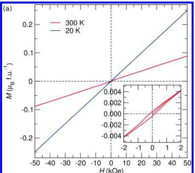
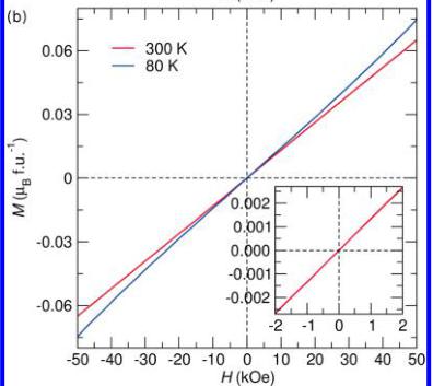
To further investigate the field dependence of the magnetic structures, we obtained isothermal magnetization curves at room temperature and just below the ordering temperature of both compounds which are illustrated in Figure 7. Both curves taken below the ordering temperature demonstrate the linear response expected from a collinear antiferromagnetic ground state. Close inspection of the room temperature traces, however, reveals the presence of some ordered ferromagnetic impurity in \( LiFeSO_{4}F \) , which is not observed in \( FeSO_{4}F \) . Such a magnetic impurity is expected to correspond to some trivalent Fe oxide impurity such as \( Fe_{3}O_{4} \) or \( Fe_{2}O_{3} \) . It is believed that the impurity was removed during the delithiation treatment which explains the absence in the \( FeSO_{4}F \) . It should be noted that the contribution from this impurity phase is saturated in a magnetic field of 1 kOe and therefore its contribution to the 10 kOe susceptibility curves is expected to be minimal. This point is confirmed by the fact that the field cooling and zero-field cooling traces lie directly on top of each other. An estimation of the amount of impurity


Figure 7. Isothermal magnetization curves for (a) \( LiFeSO_{4}F \) and (b) \( FeSO_{4}F \) obtained at various temperatures. The inset shows the low-field region of the 300 K curves demonstrating the presence of a small ferromagnetic impurity in the lithiated phase which is absent in the delithiated phase. Note that the impurity phase in the \( LiFeSO_{4}F \) was most likely washed out during the chemical oxidation, which was used to produce the \( FeSO_{4}F \) , and it is therefore not surprising that this impurity is absent in this phase.
present based on the saturation of the superimposed hysteresis loop, assuming it to be \( Fe_{2}O_{3} \) , indicates that less than 0.06% by mass of the sample is an impurity. Such a small impurity would not be expected to contribute significantly to the neutron diffraction patterns.
The high temperature region (200 to 300 K) of the inverse susceptibility, obtained in a field of 10 kOe, was fit to the Curie–Weiss equation, \( \chi = C/(T - \Theta_{\mathrm{CW}}) \) , in order to examine the spin state of the Fe and relative strength of the interactions. An effective moment of \( 4.88 \mu_{B} \) per Fe is found for \( LiFeSO_{4}F \) , which can be compared with the spin-only effective moment of \( 4.90 \mu_{B} \) expected for a single high-spin \( Fe^{2+} \) in an octahedral coordination environment \( (d^{6}, t_{2g}^{4} e_{g}^{2}, S = 2, L = 2) \) , which can be obtained from the equation \( \mu_{S} = 2 \sqrt{S(S + 1)} \) . \( FeSO_{4}F \) which contains \( Fe^{3+} \) in the same octahedral environment \( (d^{5}, t_{2g}^{3} e_{g}^{2}, S = 5/2, L = 0) \) shows an effective moment of \( 5.91 \mu_{B} \) which is also in good agreement with the expected spin-only effective moment of \( 5.92 \mu_{B} \) for a high-spin \( d^{5} \) system. A Curie–Weiss theta of -41 K is obtained for \( LiFeSO_{4}F \) while \( FeSO_{4}F \) gives a value of -194 K.
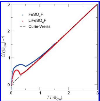
The field cooled (FC) susceptibility, scaled using the values of C and \( \Theta_{CW} \) obtained from the fit to the inverse susceptibility, is shown in Figure 8. The scaling, which has been discussed in greater detail previously, \( ^{20} \) is performed by plotting \( C/(\chi|\Theta_{\mathrm{CW}}|)-1 \) as a function of \( T/|\Theta_{\mathrm{CW}}| \) , for which Curie–Weiss behavior should yield a straight

Figure 8. Inverse magnetic susceptibility of \( LiFeSO_{4}F \) (filled red squares) and \( FeSO_{4}F \) (open blue circles) normalized as described in the text. The dashed line illustrates the expected behavior for a system which follows ideal Curie–Weiss behavior. Deviations from the dashed line above the long-range ordering temperature are reflective of short-range antiferromagnetic correlations, whereas deviations below the line reflect uncompensated interactions.
line through the origin (indicated by the dashed line) for a negative value of \( \Theta_{CW} \) . Plotting in this manner emphasizes deviations from purely Curie–Weiss behavior. It can be seen from this figure that while \( LiFeSO_{4}F \) demonstrates negative deviations from ideal Curie–Weiss behavior \( FeSO_{4}F \) has deviations that lay exclusively above the Curie–Weiss line. This negative deviation in the normalized susceptibility of \( LiFeSO_{4}F \) is traditionally interpreted as short-range correlations between spins, which is possible within the magnetic structure proposed if the two magnetic sublattices were to not precisely cancel. However, given that there is a very small amount of ferromagnetically ordered impurity, no clear conclusions can be drawn regarding this feature.
Closer examination of Figure 3b shows that \( FeSO_{4}F \) exhibits a much broader maximum, occurring over more than 200 K, than \( LiFeSO_{4}F \) . Such a broad transition suggests that the interactions more closely resemble a one-dimensional system rather than a fully three-dimensionally ordered magnetic system. We have therefore attempted to fit the data using the model of Bonner and Fisher, \( ^{21} \) where the susceptibility of a chain of classical spins can be expressed as
\[ \chi_{\mathrm{chain}}=\frac{N_{g}\beta^{2}S(S+1)}{3k_{\mathrm{B}}T}\times\frac{1+u}{1-u^{\prime}} \]
where u is the Langevin function defined as \( u = \coth((2JS(S + 1))/(k_{\mathrm{B}}T)) - ((k_{\mathrm{B}}T)/(2JS(S + 1))) \) where S = 5/2, \( k_{B} \) is the Boltzmann constant, N is Avogadro's number, g is the gyromagnetic factor of a free-electron spin, and \( \beta \) is the Bohr magneton. The result of the fit, illustrated by the dashed line in Figure 3b, gives a nearest-neighbor exchange interaction, \( J/k_{B} \) , of -16 K. Such a result confirms the one-dimensional character of \( FeSO_{4}F \) and can be compared with previous studies on the naturally occurring mineral tovarite, \( LiFePO_{4}(OH,F)^{22} \) which found values of \( J/k_{B} \) equal to -12 K. Although the tovarite sample studied in reference 22, is actually isostructural to \( LiFeSO_{4}F \) and not \( FeSO_{4}F \) , the presence of \( PO_{4} \) in place of \( SO_{4} \) groups implies that the chains of Fe will be in the trivalent oxidation state and therefore will have an exchange energy that is more directly comparable to \( FeSO_{4}F \) .
■ RESULTS AND DISCUSSION
Inspection of the neutron diffraction patterns as a function of temperature shows that no additional magnetic reflections develop
Table 4. List of Exchange Paths and Their Geometrical Characteristics for LiFeSO_{4}F
| J1 LiFeSO4F P1 | J2 LiFeSO4F P1 | J3 LiFeSO4F P1 | |
| through-space Fe-Fe distance | 3.637 Å Fe1-Fe2 | 5.205 Å Fe1-Fe1(-1,0,0) | 5.539 Å Fe2-Fe2 (0, -1, 0) |
| path type | S(a) (via F) | SS(b) | SS(b) |
| distance Fe-O (Å) | 1.992 | 2.228 | 2.144 |
| distance O-O (Å) | 2.435 | 2.404 | |
| distance O-Fe (Å) | 2.032 | 2.169 | 2.228 |
| angle Fe-O-O (deg) | 101.6 | 155.7 | |
| angle O-O-Fe (deg) | 102.3 | 107.7 | |
| torsion angle (deg) | 129.3 | 38.8 | 18.3 |
\( ^{a} \) S stands for superexchange paths. \( ^{b} \) SS stands for supersuperexchange.

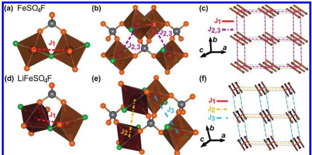
Figure 9. Illustration of the superexchange and supersuperexchange pathways considered in \( LiFeSO_{4}F \) and \( FeSO_{4}F \) . (a, d) \( J_{1} \) is the exchange pathway between neighboring irons within the chains mediated via an F atom or via a \( SO_{4} \) tetrahedron through a supersuperexchange pathway. (b, e) \( J_{2} \) and \( J_{3} \) connect iron atoms in adjacent chains, through a supersuperexchange pathway which is doubly degenerate with two distinct \( SO_{4} \) tetrahedra linking neighbors. In the case of the delithiated \( FeSO_{4}F \) compound, \( J_{2} \) and \( J_{3} \) are equivalent and are therefore labeled as \( J_{2,3} \) . (c, f) Illustration of the topology of the exchange pathways considered for \( FeSO_{4}F \) (c) and \( LiFeSO_{4}F \) (f). Note that from this topology it is clear that there is no geometrical frustration present.
after the onset of long-range order has occurred. An analysis of the relative strengths and signs of the different exchange interactions in the structures required to produce the observed magnetic structure has been done using two programs: SIMBO and ENERMAG, details of which can be found in reference 23. It should be noted that this analysis neglects the magnetocrystalline anisotropy, which plays a role in \( LiFeSO_{4}F \) using a procedure similar to that applied to other iron phosphates. \( ^{24-26} \)
The first ordered state is obtained by a calculation as a function of k (on the surface or at the interior of the Brillouin zone) and the exchange integrals. This state is given by the eigenvector corresponding to the lowest eigenvalue of the negative Fourier transform of the exchange integral matrix
\[ \xi_{i j}(\mathbf{k})=-\sum_{m}J_{i j}(\mathbf{R}_{\mathbf{m}})e^{-2\pi i\mathbf{k R}_{\mathbf{m}}} \]
where \(i\) and \(j\) refer to the magnetic atoms in a primitive cell, and \(J_{ij}(\mathbf{R}_{\mathrm{m}})\) is the isotropic exchange interaction between the spins of atom \(i\) and \(j\) in unit cells separated by the lattice vector \(\mathbf{R}_{\mathrm{m}}\).
Examination of the exchange paths in both compounds leads to different isotropic exchange interactions between magnetic atoms, all of which occur through M—O—O—M supersuperexchange pathways (two oxygen atoms involved in the path), except the nearest neighbor supersuperexchange, which occurs through the M—F—M bonds. Note that although the underlying framework of \( FeSO_{4}F \) is relatively unchanged upon intercalation of lithium, the distances and angles of the exchange paths are significantly different in the two compounds. Another significant difference comes from the fact that \( FeSO_{4}F \) crystallizes in the C2/c space group whereas \( LiFeSO_{4}F \) is triclinic. The chains are therefore more symmetrical in \( FeSO_{4}F \) than in \( LiFeSO_{4}F \) , which can be seen clearly in Figure 2.
The analysis is simplified by only considering interactions with the smallest through-space Fe—Fe distances possible. The nearest neighbor exchange, which we will denote as \( J_{1} \) , involves only Fe atoms within the same chain. It should be noted, however, that \( J_{1} \) takes into account both the Fe—F—Fe superexchange interaction as well as a supersuperexchange interaction through the \( SO_{4} \) tetrahedron which bridges neighboring octahedra. All other exchange interactions within both compounds are of supersuperexchange type through \( SO_{4} \) tetrahedra. Therefore it is assumed that contributions from nondegenerate exchange pathways will be negligible when compared with doubly degenerate pathways. These doubly degenerate pathways principally concern iron atoms which belong to adjacent chains (denoted as \( J_{2} \) and \( J_{3} \) ), and the octahedron of which are linked through two sulfate groups. For \( LiFeSO_{4}F \) , the three interactions considered are given in Table 4, and the paths between iron atoms are illustrated in panels d and e in Figure 9.
Table 5. List of Exchange Paths and Their Geometrical Characteristics for FeSO_{4}F in the Monoclinic Cell
| J_{1} FeSO_{4}F C2/c | J_{2,3} FeSO_{4}F C2/c | |
| direct distance Fe-Fe | 3.696 Å | 5.112 Å |
| path type | (intrachain interaction) S^{a} (via F) | (interchain interaction) S^{b} |
| distance Fe-O (Å) | 1.939 | 1.992 |
| distance O-O (Å) | 2.421 | 2.407 |
| distance O-Fe (Å) | 1.939 | 1.992 |
| angle Fe-O-O (deg) | 108.6 | 116.5 |
| angle O-O-Fe (deg) | 108.6 | 148.7 |
| torsion angle (deg) | 144.7 | -2.5 |
\( ^{a} \) S stands for superexchange paths. \( ^{b} \) SS stands for supersuperexchange.

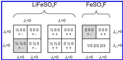
Figure 10. Magnetic phase diagrams for \( LiFeSO_{4}F \) and \( FeSO_{4}F \) . We consider three exchange integrals \( J_{1} \) , \( J_{2} \) , and \( J_{3} \) for the lithiated compound, and two exchange integrals \( J_{1} \) and \( J_{2,3} \) for the delithiated one, as \( J_{2} \) and \( J_{3} \) are geometrically equivalent because of the higher symmetry. For each domain, the different spin sequences and the corresponding propagation vector corresponding to the lowest energy (ground state) are indicated. The shaded regions correspond to the observed magnetic structure, as deduced by powder neutron diffraction.
For the delithiated \( FeSO_{4}F \) compound, the situation is simplified due to the higher symmetry of the nuclear cell. In this case, \( J_{2} \) and \( J_{3} \) connect atoms that are identical by symmetry, so that in fact \( J_{2} \) and \( J_{3} \) are the same exchange interaction. These interactions are therefore relabeled as \( J_{2,3} \) in panels b and c in Figure 9 and Table 5, and it is only necessary to consider two paths for \( FeSO_{4}F \) .
The phase diagram for the topology of this structure was calculated and the region (relative strengths and signs of the exchange interactions) corresponding to the observed magnetic structure was identified. The method discussed in references 27–30 was then used to evaluate the conditions which were satisfied by the exchange integrals in order to have the observed magnetic structure as ground state. The values of all the exchange interactions \( J_{i} \) (i = 1, 2, 3) were varied in the interval \( [-100, 100] \) . It should be noted that only relative values are important for this purpose. The k-vectors were varied inside the Brillouin zone and in special points. An auxiliary program took the output of ENERMAG and plotted a high-dimensional phase diagram using the exchange interactions as Cartesian axes. The different regions correspond to different possible magnetic structures. An analysis of the diagrams gives us immediately the conditions that the exchange integrals have to satisfy to give, as the first ordered state, the observed magnetic structure. For \( LiFeSO_{4}F \) , the magnetic phase diagram obtained with different relative values of \( J_{1} \) , \( J_{2} \) , and \( I_{3} \) is displayed in the left panel of Figure 10. The observed propagation vector is \( \mathbf{k} = \left( \frac{1}{2}, \frac{1}{2}, 0 \right) \) , and the spin arrangement is the following \( (+ -) \) , i.e., antiparallel arrangement between Fe1 ( \( 0\ 0\ \frac{1}{2} \) ) and Fe2 ( \( 0\ 0\ 0 \) ). This magnetic structure is found as the ground state when \( J_{1} \) , \( J_{2} \) , and \( \mathbf{J}_{3} \) are all negative.
The phase diagram of \( FeSO_{4}F \) is displayed in the right panel of Figure 10. The most significant difference between the two observed magnetic structures comes from the difference in the sign of the interchain exchange interactions \( (J_{2}, J_{3}, \text{and } J_{2,3}) \) that become positive. This change in sign is believed to be related to changes in the bond angles of the Fe—O—O—Fe pathway which can be seen in panels b and e in Figure 9 because the introduction of Li into \( FeSO_{4}F \) significantly changes these angles when it bonds to the F.
According to the Goodenough–Kanamori–Anderson rules for superexchange, \( ^{31-33} \) the interaction between two Fe-ions with half-filled orbitals through a bridging anion is strongly antiferromagnetic (corresponding to a negative sign in the convention used) when the superexchange angle is close to \( 180^{\circ} \) . The interaction weakens as the angle progressively closes and changes the sign to be ferromagnetic when the angle is close to \( 90^{\circ} \) . This is clearly verified in the present case. While \( J_{1} \) must remain negative for both compounds, it can be seen from Figure 9 and Tables 4 and 5 that there is a change in the M—F—M bond angle from \( 145^{\circ} \) in \( FeSO_{4}F \) to \( 129^{\circ} \) in \( LiFeSO_{4}F \) . This change in bond angle is a consequence of bonding between Li and F which causes the F position to shift such that a bond of reasonable length can be formed. Such a significant change in the principal superexchange pathway offers an explanation for the difference in the ordering temperature since this change in bond angle greatly reduces the degree of orbital overlap between the Fe and F orbitals weakening the exchange interaction \( J_{1} \) . The lowering of the ordering temperature can also be attributed to changes in the oxidation state from \( Fe^{3+} \) ( \( d^{5} \) ) to \( Fe^{2+} \) ( \( d^{6} \) ). The \( d^{5} \) configuration of the trivalent iron gives a classical spin configuration whereas the addition of an extra electron will begin to occupy antibonding orbitals, giving rise to magnetocrystalline anisotropy from the orbital degeneracy. This point is further reinforced by comparing the ordering temperature of the previously reported \( LiFePO_{4}(OH,F) \) tovarite phase which, while isostructural to \( LiFeSO_{4}F \) , exhibits an antiferromagnetic ordering temperature closer to \( 80 K \) , \( ^{34} \) which clearly shows the oxidation state is important in determining at what point the system establishes antiferromagnetic order. Using the same argument, the increasing population of the antibonding orbitals, one can easily understand that \( T_{N} \) decreases from 25 to 18 K to 12 K as we move from Fe to Co and Ni within the \( LiMSO_{4}F \) series.
■ CONCLUSIONS
In this contribution, we have reported on the nature of the magnetic order found in \( LiFeSO_{4}F \) and \( FeSO_{4}F \) . Both compounds are quasi-one-dimensional magnetic chains which establish an antiferromagnetic ground state below the ordering temperature. Using neutron diffraction and detailed magnetic susceptibility analysis we demonstrate a significant decrease in the ordering temperature from 100 K in \( FeSO_{4}F \) to 25 K in \( LiFeSO_{4}F \) . We have shown that this lowering of the ordering temperature, besides being affected by decreasing the Fe oxidation state from 3+ to 2+, is also the result of bond formation.
between Li and F which causes the principle superexchange angle to move away from the ideal \( 180^{\circ} \) and thereby decrease magnetic interactions along the length of the chain. We have also found that this change in the structure reduces interactions between the chains causing \( FeSO_{4}F \) to show a temperature dependent susceptibility which closely resembles that of a one-dimensional chain system as confirmed by data fitting. We have also presented the magnetic structures and clearly explained the interplay between the structure and magnetism with these Fe-based fluorosulfates. A similar type of structural-magnetic study, using neutron diffraction, is being conducted on the \( AMSO_{4}F \) phases (A = Li, Na; M = Co and Ni) homologues. Few subtle structure changes in the magnetic structure, which will be reported in a forthcoming paper, are observed.
AUTHOR INFORMATION
Corresponding Author
\( ^{*} \) E-mail: gwenaelle.roussé@upmc.fr (G.R.); jean-marie.tarascón@u-picardie.fr (J.-M.T.).
ACKNOWLEDGMENT
We thank Michella Brunelli for her help during neutron diffraction experiments at ILL and Ram Seshadri for helpful discussion regarding the magnetic measurements. MK is supported through a Materials World Network Grant from the National Science Foundation (DMR 0909180), and acknowledges the use of MRL Central Facilities, supported by the MRSEC Program of the NSF (DMR 0520415); a member of the NSF-funded Materials Research Facilities Network (www.mrfn.org).
■ REFERENCES
(1) Pahdi, A. K.; Nanjundasvamy, K. S.; Masquelier, C.; Goodenough, J. B. J. Electrochem. Soc. 1997, 144, 2581–2586. Pahdi, A. K.; Manivannan, M.; Goodenough, J. B. J. Electrochem. Soc. 1998, 145, 1518–1520.
(2) Padhi, A. K.; Nanjundaswamy, K. S.; Goodenough, J. B. J. Electrochem. Soc. 1997, i44, 1188–1194.
(3) Recham, N.; Chotard, J.-N.; Dupont, L.; Delacourt, C.; Walker, W.; Armand, M.; Tarascon, J. M. Nat. Mater. 2010, 9, 68–74.
(4) Tarascon, I. M.; Recham, N.; Armand, M.; Chotard, J.-N.; Barpanda, P.; Walker, W.; Dupont, L. Chem. Mater. 2010, 22, 724–739.
(5) Recham, N.; Chotard, J.-N.; Jumas, J. C.; Laffont, L; Armand, M.; Tarascon, J. M. Chem. Mater. 2010, 22, 1142–1148.
(6) Ati, M.; Sougraty, M. T.; Recham, N.; Barpanda, P.; Leriche, J. B.; Courty, M.; Armand, M.; Tarascon, J. M. J. Electrochem. Soc. 2010, 157, A1007–A1015.
(7) Ati, M.; Walker, W. T.; Djellab, K.; Armand, M.; Recham, N.; Tarascon, J. M. Electrochem. Solid-State Lett. 2010, 13, A150–A153.
(8) Tripathi, R.; Ramesh, T. N.; Ellis, B. L.; Nazar, L. F. Angew. Chem., Int. Ed. 2010, 49, 8738–8742.
(9) Melot, B. C.; Goldman, A.; Darago, L. E.; Furman, J. D.; Rodriguez, E. E.; Seshadri, R. J. Phys.: Condens. Matter 2010, 22, 506003.
(10) Masuda, T; Zheludev, A; Roessli, B; Bush, A; Markina, M; Vasiliev, A. Phys. Rev. B 2005, 72, 014405.
(11) Rodriguez-Carvajal, J. Physica B 1993, 192, 55; see http://www.ill.eu/sites/fullprof/.
(12) Rietveld, H. M. J. Appl. Crystallogr. 1969, 2, 65.
(13) Brown, I. D.; Altermatt, D Acta Crystallogr., Sect. B 1985, 41, 244.
(14) Hiroi, Z.; Takano, M. Nature 1995, 377, 41–43.
(15) Bertaut, E. F. J. Phys. 1971, 32, C1.
(16) Rodriguez-Carvajal, J. BASIREPS-A Program for Calculating Non-Normalized Basis Functions of the Irreducible Representations of the Little Group \( G_{k} \) for Atom Properties in a Crystal; Laboratoire Leon Brillouin, CEA Saclay: Gif sur Yvette, France, 2004.
(17) Rousse, G.; Rodríguez-Carvajal, J.; Wurm, C.; Masquelier, C. Chem. Mater. 2001, 13, 4527.
(18) Liang, G.; Park, K.; Li, J.; Benson, R. E.; Vaknin, D.; Markert, J. T.; Croft, M. C. Phys. Rev. B 2008, 77, 064414.
(19) Wollan, E. O.; Koehler, W. C. Phys. Rev. 1955, 100, 545–563.
(20) Melot, B. C.; Drewes, J. E.; Seshadri, R.; Stoudenmire, E. M.; Ramirez, A. P. J. Phys.: Condens. Matter 2009, 21, 216007.
(21) Bonner, J. C.; Fisher, M. E. Phys. Rev. A 1964, 135, 640.
(22) Pizarro-Sanz, J. L.; Dance, J. M.; Villeneuve, G.; Arriortua-Marcaiada, M. I. Mater. Lett. 1994, 18, 327–330.
(23) El Khayati, N.; Cherkaoui, El M. R.; Rodriguez-Carvajal, J.; André, G.; Blanchard, N.; Bouree, F.; Collin, G.; Roisnel, T. Eur. J. Phys. 2001, B22, 429.
(24) Mentre, O.; Bouree, F.; Rodriguez-Carvajal, J.; El Jazouli, A.; El Khayati, N.; Ketatni, El M. J. Phys: Condens. Matter 2008, 20, 415211.
(25) Rousse, G.; Wurm, C.; Masquelier, C.; Rodriguez-Carvajal, J. Solid State Sci. 2002, 4, 973.
(26) Rousse, G.; Rodriguez-Carvajal, J.; Patoux, S.; Masquelier, C. Chem. Mater. 2003, 15, 4082–4090.
(27) Yoshimori, A. J. Phys. Soc. Jpn. 1959, 14, 807.
(28) Villain, J. J. Phys. Chem. Solids 1959, 11, 303.
(29) Lyons, D. H.; Kaplan, T. Phys. Rev. 1960, 120, 1580.
(30) Freiser, M. J. Phys. Rev. 1961, 123, 2003.
(31) Goodenough, J. B. Phys. Rev. 1960, 117, 1442–1451.
(32) Kanamori, J. J. Phys. Chem. Solids 1959, 10, 87–98.
(33) Anderson, P. W. Phys. Rev. 1950, 79, 350–356.
(34) Pizarro-Sanz, J. L.; Dance, J. M.; Villeneuve, G.; Arriortua-Marcaiada, M. I. Mater. Lett 1994, 18, 327–330.
 p1_0.jpg
 p2_0.jpg
 p3_0.jpg
 p3_1.jpg
 p3_2.jpg
 p4_0.jpg
 p4_1.jpg
 p4_2.jpg
 p5_0.jpg
 p6_0.jpg
 p6_1.jpg
 p6_2.jpg
 p7_0.jpg
 p8_0.jpg