| Transition Temperature | 20 K |
|---|---|
| Experiment Temperature | 2 K |
| Propagation Vector | k1 (0, 0, 0) |
| Parent Space Group | Fd-3m (#227) |
| Magnetic Space Group | Fd'd'd (#70.530) |
| Magnetic Point Group | m'm'm (8.4.27) |
| Lattice Parameters | 10.20810 10.20810 10.20810 90.00 90.00 90.00 |
|---|---|
| DOI | 10.1016/j.jpowsour.2013.08.125 |
| Reference | R. Martinez-Coronado, J. Alonso, V. Cascos and M. Fernandez-Diaz, Journal of Power Sources (2014) 247 876-882. |
Crystal and magnetic structure of the Bi₂RuMnO₇ pyrochlore: A potential new cathode for solid oxide fuel cells
R. Martínez-Coronado \( ^{a,*} \) , J.A. Alonso \( ^{a} \) , V. Cascos \( ^{a} \) , M.T. Fernández-Díaz \( ^{b} \)
\( ^{a} \) Instituto de Ciencia de Materiales de Madrid, C.S.I.C., Cantoblanco, E-28049 Madrid, Spain
\( ^{b} \) Institut Laue Langevin, BP 156X, Grenoble F-38042, France
HIGHLIGHTS
• A new pyrochlore-like phase of composition \( Bi_{2}RuMnO_{7} \) has been prepared.
• NPD data unveils a cation disorder of Mn and Bi atoms between A and B positions.
• Antiferromagnetic coupling of two subsets of \( Mn^{4+}/Ru^{4+} \) spins. • Conductivity values at SOFCs working temperatures between 39 and 28 \( Sm^{-1} \) .
• Output power densities of \( 360 \, mW cm^{-2} \) at \( 850 \, ^{\circ}C \) .
ARTICLE INFO
Article history: Received 28 June 2013 Received in revised form 27 August 2013 Accepted 28 August 2013 Available online 18 September 2013
Keywords: Cathode SOFC \( R_{2}RuMnO_{7} \) \( Bi_{2}Ru_{2}O_{7} \) Neutron diffraction
A B S T R A C T
A new pyrochlore-like phase of composition \( Bi_{2}RuMnO_{7} \) has been prepared as polycrystalline powder, structurally characterized from X-ray diffraction (XRD) and neutron powder diffraction (NPD) data, in complement with magnetic and transport measurements, and finally tested as cathode material for solid-oxide fuel cells (SOFCs). \( Bi_{2}RuMnO_{7} \) pyrochlore is defined in a cubic unit cell with space group \( Fd-3m \) ; the structural analysis from NPD data unveils a singular feature consisting of a cation disorder of Mn and Bi atoms between A and B positions. This disorder leads to the reduction of \( Mn^{4+} \) at B position to \( Mn^{2+} \) at A position and the oxidation of \( Bi^{3+} \) at A position to \( Bi^{5+} \) at B position. The low-temperature NPD data indicates an antiferromagnetic coupling of two subsets of \( Mn^{4+}/Ru^{4+} \) spins, demonstrating that the magnetic frustration is partially relieved by the random distribution of Mn and Ru over the 16c sites. The obtained compound displays a metallic-like behavior with conductivity values at the SOFCs working temperatures (650–850 °C) that span between 39 and 28 \( Sm^{-1} \) . \( Bi_{2}RuMnO_{7} \) shows good performance working as a cathode with LSGM electrolyte, yielding output power densities of 360 mW cm \( ^{-2} \) at 850 °C with pure \( H_{2} \) as a fuel.
© 2013 Elsevier B.V. All rights reserved.
1. Introduction
Nowadays, one of the biggest challenges to accomplish the development of solid-oxide fuel cells (SOFCs) as economically viable energy-conversion devices is the decrease in the operating temperature (550–850 °C) without incurring in the deterioration of the effectiveness of the cell. The cathode is responsible for a significant drop in the cell potential at intermediate temperatures (650–850 °C), therefore the development of a mixed ionic-electronic conductor (MIEC) oxide performing as a cathode with an appropriate conductivity and catalytic activity in the oxygen reduction reaction is an important issue in solid state chemistry.
Pyrochlore oxides with the composition A2B2O7, which in general crystallize in the cubic, face-centered space group Fd-3m \( ^{[1]} \) , are an extremely interesting alternative to the most commonly used perovskite oxides, due their open structure combined with a high chemical and structural flexibility that allow tuning the adequate properties for specific applications. Oxygen-stoichiometric pyrochlores where A and B cations are fully ordered often have a poor conductivity of oxide anions. However, the presence of a cationic disorder favors the formation of Frenkel defects responsible for the oxide-ion diffusion in these materials \( ^{[2,3]} \) . In the \( A_{2}B_{2}O_{7} \) pyrochlore structure, the A and B cations can undergo some antisite disordering in partially disordered structures, many times associated with the presence of substantial
amounts of oxygen vacancies, well supported by this structural type.
Concerning the nature of the cations at the B sites, Ru is an interesting element promoting good electrical and catalytic properties. Ruthenate pyrochlores \( \left(\mathrm{Bi}_{2}\mathrm{Ru}_{2}\mathrm{O}_{7}\right. \) or \( \left.\mathrm{Pb}_{2}\mathrm{Ru}_{2}\mathrm{O}_{6}\right) \) are characterized by high electronic conductivity \( (10-1000\ \mathrm{Scm}^{-1} \) at room temperature [4]), a high catalytic activity for oxygen reduction as well as for oxygen evolution. They also show technological importance as electrode materials in IT-SOFC [5-7]. Moreover, ruthenium pyrochlores \( A_{2}Ru_{2}O_{7} \) show unusual electronic properties [8-10], since Ru 4d electrons are borderline between localized and itinerant, and depending on the nature of the A-type cation the materials are either metallic Pauli paramagnets, e.g. \( Bi_{2}Ru_{2}O_{7} \) , or semiconductors with a spontaneous ruthenium localized ionic moment, e.g. \( Y_{2}Ru_{2}O_{7} \) . The electrochemical activity of this mixed-oxide type is believed to be related to variable oxidation states available for ruthenium, and consequently to oxygen stoichiometry [11]. However, Ru-based compounds have a high chemical instability with CGO or YSZ electrolytes [12,13]. On the other hand, Mn-based pyrochlores exhibit an excellent stability together with very interesting electrical properties [14,15].
Recently we have prepared and characterized new \( R_{2}RuMnO_{7} \) phases \( [16-18] \) that have been described as potential cathodes for solid-oxide fuel cells, based upon a mixed electronic and ionic conductivity. These phases are stable in oxidizing conditions, as required for cathode materials. Inspired in the paradigmatic properties of \( Bi_{2}Ru_{2}O_{7} \) , we have designed a novel oxide where half of Ru positions are replaced by Mn, yielding the \( Bi_{2}MnRuO_{7} \) composition.
In this work the \( Bi_{2}RuMnO_{7} \) pyrochlore oxide has been prepared and exhaustively characterized from X-ray and neutron diffraction data, in complement with conductivity, dilatometry and magnetic measurements. Its performance as cathode material has been evaluated in electrolyte-supported single cells using \( SrMo_{0.8}Fe_{0.2}O_{3-\delta} \) (SMFO) as anode [19] and \( La_{0.8}Sr_{0.2}Ga_{0.83}Mg_{0.17}O_{3-\delta} \) (LSGM) as electrolyte, with \( H_{2} \) as a fuel.
2. Experimental procedure
\( Bi_{2}RuMnO_{7} \) oxide was prepared by a wet chemistry procedure. This method requires the formation of very reactive precursors starting from an aqueous solution of the metal ions and citric acid. Stoichiometric amounts of \( Bi_{2}O_{3} \) , \( MnCO_{3} \) were solved in citric acid and some drops of nitric acid, whereas \( RuO_{2} \) powder remained in suspension under magnetic stirring; the suspension was slowly dehydrated by gentle heating, leading to organic resins that contain a homogeneous distribution of the involved cations. The formed resins were dried at 120 °C, decomposed at 600 °C for 12 h, and the organic materials and the nitrates were eliminated in a subsequent treatment at 800 °C in air, for 2 h. This treatment gave rise to finely divided and homogeneous precursor materials that finally were heated in air at 1000 °C for 12 h to obtain a pure pyrochlore oxide phase.
The initial characterization was performed by XRD using a Bruker-AXS D8 Advanced diffractometer (40 kV, 30 mA), controlled by a DIFFRACT \( ^{PLUS} \) software, in Bragg-Brentano reflection geometry with Cu K \( _{\alpha} \) radiation ( \( \lambda = 1.5418 \) Å) and a PSD (Position Sensitive Detector). A filter of nickel allows the complete removal of Cu K \( _{\beta} \) radiation. The slit system was selected to ensure that the X-ray beam was completely within the sample for all 2 \( \theta \) angles. The data were obtained between 10 and 100° 2 \( \theta \) in steps of 0.05°. Neutron powder diffraction (NPD) experiments were carried out at the ILL in Grenoble, using the high-resolution powder diffractometer D1A ( \( \lambda = 1.910 \) Å) at room temperature in order to study the crystallographic structure. The high-flux medium-resolution D1B diffractometer ( \( \lambda = 2.520 \) Å) was utilized for the study of the magnetic structures and the analysis of its thermal evolution; a set of sequential NPD patterns were collected in the temperature interval T = 2–80 K, with the sample set in a standard “orange” cryostat. NPD data were analyzed by the Rietveld method [20] using the Fullprof program [21]. A pseudo-Voigt function was chosen to generate the line shape of the diffraction peaks. The following parameters were refined in the final run: scale factor, background coefficients, zero-point error, pseudo-Voigt corrected for asymmetry parameters, positional coordinates and isotropic thermal factors for all the atoms.
The magnetic measurements were performed in a commercial superconducting quantum interference device (SQUID) magnetometer. ZFC (zero field-cooled) and FC (field-cooled) dc magnetic susceptibility data were collected in the \( 5 \leq T \leq 300 \) K range under an applied magnetic field of 0.1 T. Isothermal magnetization curves were obtained for magnetic fields going from -5 T to 5 T at T = 4 K.
For the measurements of the thermal expansion coefficient and electrical conductivity the use of sintered samples is required. Disk-shaped pellets of 6 mm of diameter pressed at 1 ton were heated in air at 900 °C for 12 h. The obtained densities were between 90 and 95%. The thermal expansion behavior of the sintered samples was evaluated in a dilatometer Linseis L75HX1000, between 100 and 900 °C in air. The conductivity was measured between 25 and 850 °C in air, by the four-point method in bar-shaped pellets (10 mm large × 3 mm width × 3 mm) under dc currents between 100 and 300 mA. Electrical measurements were performed by decreasing temperature from 850 to 25 °C at 3 °C min \( ^{-1} \) . The sample was stabilized for 10 min at each temperature before the electrical test. The currents and voltages were applied and collected with a Potentiostat–Galvanostat AUTOLAB PGSTAT 302 from ECO CHEMIE.
Single cell tests were carried out using \( La_{0.8}Sr_{0.2}Ga_{0.83}gMg_{0.17}O_{3-\delta} \) (LSGM) pellets as electrolyte, \( Bi_{2}RuMnO_{7} \) (BRMO) as cathode material, and \( SrMo_{0.8}Fe_{0.2}O_{3-\beta} \) (SMFO) as anode material [19]. LSGM pellets of 20-mm diameter were sintered at 1450 °C for 20 h and then polished with a diamond wheel to a thickness of 300 \( \mu \) m. \( La_{0.4}Ce_{0.6}O_{2-\delta} \) (LDC) was used as a buffer layer between the anode and the electrolyte in order to prevent the interdiffusion of ionic species. Inks of LDC, SMFO and BRMO were prepared with a binder (V-006 from Heraeus). For the test, LDC ink was screen-printed onto one side of the LSGM disk followed by a thermal treatment at 1300 °C in air for 1 h. SMFO was subsequently screen printed onto the LDC layer and fired at 1100 °C in air for 1 h. BRMO was finally screen printed onto the other side of the disk and fired at 900 °C in air for 2 h. The working electrode area of the cell was 0.24 cm \( ^{2} \) (0.6 cm × 0.4 cm). Au gauze with small amounts of Au paste in separate dots was used as current collector at both the anodic and the cathodic sides for ensuring electrical contact. The cells were tested in a vertical tubular furnace at 800 and 850 °C; the anode side was fed with pure \( H_{2} \) , with a flow of 20 mL min \( ^{-1} \) , whereas the cathode worked in an air flow of 100 mL min \( ^{-1} \) . The fuel-cell tests were performed with an AUTOLAB 302N Potentiostat/Galvanostat by decreasing the voltage of the cell from open circuit voltage (OCV) to 0.1 V, with steps of 0.010 V, holding 10 s at each step. Current density was calculated by recording the current flux through the effective area of the cell.
Scanning electron microscopy (SEM) images were collected with a Hitachi S-3000N and an analyzer from Oxford Instrument, model INCAtx-sight.
3. Results and discussion
3.1. Crystallographic characterization
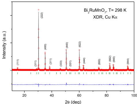
\( Bi_{2}RuMnO_{7} \) oxide was obtained as well-crystallized polycrystalline powder. The XDR diagram, shown in Fig. 1, is
characteristic of a pyrochlore-type structure of formula \( A_{2}B_{2}O_{7} \) . The diagram can be indexed in a cubic, face-centered unit cell, as shown in the figure. No impurity phases were detected.
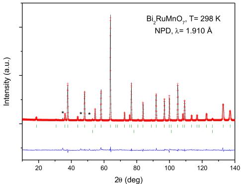
To carry out a more accurate structural study of the \( Bi_{2}RuMnO_{7} \) , we performed NPD measurements at room temperature. The crystal structure is defined in the cubic Fd-3m space group, with origin at \( (1/8, 1/8, 1/8) \) . In this setting, the Bi cations are placed at 16d \( (1/2, 1/2, 1/2) \) sites, the Mn and Ru cations are distributed at random at 16c \( (0, 0, 0) \) position and the two kinds of nonequivalent oxygen atoms are located: O1 at 48f \( (x, 1/8, 1/8) \) and O2 at 8b \( (3/8, 3/8, 3/8) \) sites.
The above-described canonical model yielded very high discrepancy factors, with \( R_{Bragg} \) higher than 35%, clearly indicating that a singular structural feature had been overlooked in this preliminary description. In a second run, some Mn atoms were allowed to be placed at the 16d positions together with Bi atoms (with the \( (\mathrm{Bi},\mathrm{Mn}) \) occupancy constrained to unity); also some Bi atoms were allowed to be placed at the 16c positions together with Mn and Ru atoms (with the \( (\mathrm{Mn},\mathrm{Ru},\mathrm{Bi}) \) occupancy constrained to unity), leading to a substantial improvement of the fit. As there is a coexistence of three different cations, Ru, Mn and Bi; therefore some constraints need to be introduced. The occupancy of Ru at the 16c sites was fixed to 0.8, 0.9, 1.0, 1.1, 1.2, and 1.3 and then refined the Bi/Mn ratio independently at A and B sites. A more detailed description of the refinement procedure is included as Supplementary information. A final discrepancy factor of \( R_{Bragg} = 3.83\% \) was obtained. In fact, neutrons are specially suited to distinguish between Mn ( \( -3.73 \) fm) and Ru (7.03 fm) or Bi (8.53 fm), given their contrasting scattering lengths. Therefore, the refinement of the mixed occupancy factors of the cations at A and B sublattices shows that there is a noticeable disorder of Mn and Bi between both positions. The occupancy of O2 oxygen atoms was also refined, giving a slight deviation from the full stoichiometry; the occupancy factor of O1 oxygen atoms converged to values slightly higher than the unity, thus it was fixed to 1.00. This oxide exhibits a redox balance between \( Bi^{3+} \) (at A position) and \( Mn^{4+} \) (at B position) where the oxygen sublattice seems not to be significantly affected. After the different trial refinements indicated in the Supplementary information, the most chemically convincing result is the one finally selected, containing 1.2 Ru at B, as \( Bi_{1.571(1)}Mn_{0.43(1)}-Ru_{1.2}Mn_{0.305(12)}Bi_{0.495(12)}O_{7} \) . In this model the Bi/Ru ratio is 1.72 (instead of 2 for the nominal stoichiometry), which suggests some Bi volatilization, and, besides, it implies an oxygen contents of 7.03, which is within the error bars of that determined in the neutron refinement. The thermal factor of A atoms, of \( 1.2\ \AA^{2} \) , has been consistent in the different models tried. Its elevated value may be due to the different coordination and bond lengths required by \( Bi^{3+} \) (with an electron lone pair) and \( Mn^{2+} \) , requiring spherical symmetry, distributed at random at this site. Anyway, large thermal factors are commonly observed at the A-sites of pyrochlore oxides [22,23].
After the full refinement of the structure we achieved a good agreement between the observed and calculated NPD patterns at room temperature, illustrated in Fig. 2. Table 1 summarizes the unit-cell, atomic positions, occupancies, displacement parameters and discrepancy factors after the Rietveld refinement of \( Bi_{2}RuMnO_{7} \) at room temperature, and Table 2 contains the main interatomic distances and angles.
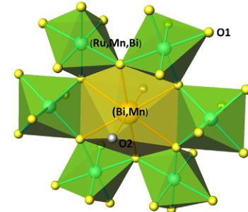
Fig. 3 displays a view of the crystal structure, highlighting the structural disorder determined by NPD. The B-type atoms, Ru, Mn and Bi are distributed at random at the octahedral positions; the octahedra share corners with B–O–B Bi angles of \( 133.72^{\circ} \) , forming interconnected cavities in a covalent three-dimensional network. A-type atoms, Bi and Mn, also randomly distributed, are eight-fold coordinated to six O1 oxygen atoms at equal distances plus two O2 oxygen atoms at smaller distances in a scalenohhedron (distorted cube).

Fig. 1. XRD patterns of \( Bi_{2}RuMnO_{7} \) , indexed in a cubic unit-cell with \( a \approx 10 \AA \) .
Assuming \( Bi^{3+} \) and \( Mn^{2+} \) valences at A position, and \( Mn^{4+} \) , \( Ru^{4+} \) and \( Bi^{5+} \) at the octahedral B sites, the required charge neutrality is perfectly achieved for the oxygen contents also determined from NPD data. There are examples of pyrochlore oxides containing \( Bi^{5+} \) at the B positions [24,25], since \( Bi^{5+} \) ionic size (0.76 Å) is well suited to be accommodated at the octahedral sites, whereas \( Bi^{3+} \) (1.03 Å) would be too large, and the presence of the lone electron pair would require a much more irregular environment. In the same way, there are previous examples of pyrochlore oxides containing \( Mn^{2+} \) at the A sites [17,26], since its ionic radius (0.96 Å) is also adequate for the scalenoidal environment. In these cases the contrast between the negative scattering length of Mn and other atoms with positive scattering factor is clearly highlighted in the neutron refinements. The presence of 1st transition metal ions on A-sites has recently been reported in other related systems [27,28] and this adds credibility to the possible migration of Mn to these sites.
A significant contraction of the lattice is observed as Ru is half-replaced by Mn; the unit-cell parameter shrinks from \( 10.2934(1)\ \AA \) for \( Bi_{2}Ru_{2}O_{7} \) [29] to \( 10.2104(1)\ \AA \) for \( Bi_{2}RuMnO_{7} \) . The contraction of the lattice is a result of the smaller ionic radius of \( \mathrm{Mn^{4+}} \) ( \( 0.53\ \AA \) ).

Fig. 2. Comparison of the observed (crosses), calculated (solid line), and difference (at the bottom) NPD patterns for \( Bi_{2}RuMnO_{7} \) at 298 K. The two series of tick marks correspond to the positions of the allowed Bragg reflections for the main phase and vanadium from the sample holder. \( {}^{\dagger} \) corresponds to an unidentified impurity.
Unit-cell parameters, atomic positions, occupancies, displacement factors, magnetic moments and reliability factors of \( Bi_{2}RuMnO_{7} \) in the cubic \( Fd-3m \) (no. 227) space group, from NPD data at 298 K (D1A data) and 2 K (D1B data). \( Bi/Mn \) are placed at 16d (1/2, 1/2, 1/2), Mn/Ru/Bi at 16c (0, 0, 0), O1 at 48f (x, 1/8, 1/8), O2 at 8b (3/8, 3/8, 3/8) positions.
| 298 K | 2 K | |
| a ( \( \textup{\AA} \) ) | 10.2104 (1) | 10.2081 (1) |
| V ( \( \textup{\AA}^{3} \) ) | 1064.46 (2) | 1063.93 (2) |
| Bi/Mn (1/2, 1/2, 1/2) | ||
| B \( _{\textup{iso}} \) ( \( \textup{\AA}^{2} \) ) | 1.26 (7) | 1.27 (2) |
| f \( _{\textup{occ}} \) Bi/Mn (%) | 0.78 (1)/0.22 (1) | 0.78/0.22 |
| Ru/Mn/Bi (0, 0, 0) | ||
| B \( _{\textup{iso}} \) (\( \textup{\AA}^{2} \) ) | 0.493 (1) | 0.501 (2) |
| f \( _{\textup{occ}} \) Ru/Mn/Bi (%) | 0.60/0.15 (1)/0.25 (1) | 0.60/0.15/0.25 |
| O1 (x, 1/8, 1/8) | ||
| x | 0.3261 (1) | 0.3260 (1) |
| B \( _{\textup{iso}} \) ( \( \textup{Å}^{2} \) ) | 0.499 (5) | 0.510 (1) |
| f \( _{\textup{occ}} \) | 1.000 | 1.000 |
| O2 (3/8, 3/8, 3/8) | ||
| B \( _{\textup{iso}} \) (\(\textup{\AA}^{2}\)) | 1.28 (4) | 1.28 (2) |
| f \( _{\textup{occ}} \) | 0.99 (1) | 0.99 |
| Mag. mom. Mn ( \( \mu_{\textup{B}} \) ) | 1.78 (2) | |
| Rel. factors | ||
| \( \chi^{2} \) | 4.12 | 5.50 |
| R \( _{\textup{p}} \) (%) | 4.06 | 2.41 |
| R \( _{\textup{vap}} \) (%) | 5.02 | 3.06 |
| R \( _{\textup{exp}} \) (%) | 3.14 | 1.36 |
| R \( _{\textup{mag}} \) (%) | 10.25 | |
| R \( _{\textup{l}} \) (%) | 3.55 | 3.50 |
compared to that of \( Ru^{4+} \) (0.62 Å) in sixfold coordination [30]. The obtained value for the \( (\mathrm{Ru},\mathrm{Mn},\mathrm{Bi}) \) -O1 interatomic distance, which is 1.978 (2) Å (Table 2), is close to the expected from the ionic radii of \( \mathrm{Mn}^{4+} \) (0.53 Å), \( Ru^{4+} \) (0.62 Å), \( Bi^{5+} \) (0.76 Å) and \( O^{2-} \) (1.40 Å) [30], which is 2.041 Å for the determined crystallographic formula. The observed \( (\mathrm{Bi},\mathrm{Mn}) \) -O distances at A-sites, of 2.4601 are also in good agreement with those expected from the ionic radii sum, of 2.465.
3.2. Magnetic measurements
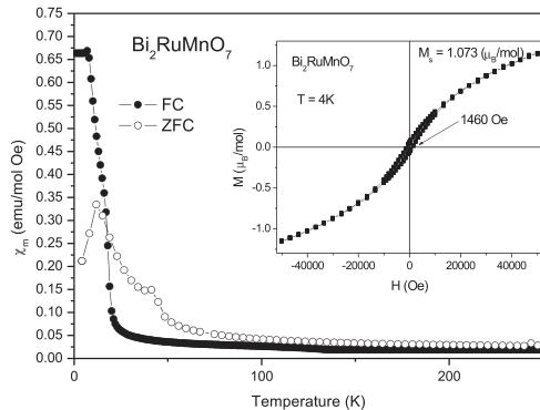
The FC (field cooling) and ZFC (zero field cooling) dc magnetic susceptibility vs. temperature has been measured for the \( Bi_{2}RuMnO_{7} \) pyrochlore between 5 and 300 K. Fig. 4 illustrates the FC curves, showing an abrupt increase of the susceptibility at 20 K, suggesting the onset of magnetic ordering of the Mn and Ru cations. The ZFC and FC curves that overlap at high temperatures diverge on decreasing the temperature, indicating magnetic irreversibilities or frustration.
The isothermal magnetization curve, measured at 4 K, is displayed in the inset of Fig. 4. It shows a narrow hysteresis loop (coercive field \( H_{c} = 1460 \, Oe \) ), and a curvature characteristic of ferromagnetic interactions over imposed with an antiferromagnetic response. The magnetization overcomes \( 1 \, \mumol^{-1} \) at high
Selected atomic distances ( \( \AA \) ) and angles ( \( ^{\circ} \) ) for \( Bi_{2}RuMnO_{7} \) at 298 and 2 K.
| T (K) | 298 K | 2 K |
| Distance ( \( \AA \) ) | ||
| \( (Bi,Mn)-O1 \) (x6) | 2.5413 (2) | 2.5312 (2) |
| \( (Bi,Mn)-O2 \) (x2) | 2.2182 (4) | 2.2102 (3) |
| \( (Bi,Mn-O) \) | 2.4605 | 2.4510 |
| \( (Mn,Ru,Bi)-O1 \) (x6) | 1.978 (2) | 1.964 (4) |
| Angles ( \( ^{\circ} \) ) | ||
| \( (Mn,Ru,Bi)-O1-(Mn,Ru,Bi) \) | 133.72 (2) | 133.41 (2) |
| O1-(Mn,Ru,Bi)-O1 | 84.94 (2) | 84.72 (2) |

Fig. 3. View of the crystal structure of \( Bi_{2}RuMnO_{7} \) : the octahedral units are randomly occupied by Ru, Mn and Bi atoms; the scalenoidal environment contains Bi and Mn.

Fig. 4. Thermal evolution of the ZFC/FC magnetic susceptibility for \( Bi_{2}RuMnO_{7} \) . Inset: magnetization vs. magnetic field isotherms at \( T = 4 \, K \) .
applied magnetic fields, although it does not present saturation at the maximum field of 5 T.
3.3. Determination of the magnetic structure
The thermal evolution of the magnetic structure of \( Bi_{2}MnRuO_{7} \) was followed from the sequential D1B NPD data collected with

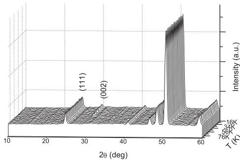
Fig. 5. Thermal evolution of the NPD patterns measured for \( Bi_{2}RuMnO_{7} \) between 5 and 80 K collected at D1B diffractometer with \( \lambda = 2.520 \) Å. Below 45 K there is a magnetic contribution to the scattering on the (002) reflection.

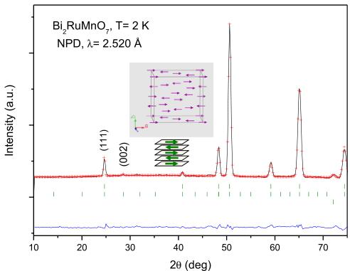
Fig. 6. Comparison of the observed (crosses), calculated (solid line), and difference (at the bottom) NPD patterns for \( Bi_{2}RuMnO_{7} \) at 2 K. The three series of markers correspond to the positions of the allowed Bragg reflections for the crystallographic phase, the magnetic reflections and vanadium from the sample holder. The inset shows a schematic view of the magnetic structures where the orientation of the magnetic moments is coplanar with the AFM layers.
2.520 Å in the temperature interval \( T = 2-80 \) K. Fig. 5 illustrates the NPD patterns sequentially obtained in this temperature range. The low-angle (111) reflection increases in intensity upon cooling and also, there is a magnetic contribution on the (002) peak below 45 K that totally vanishes at higher temperatures.
The magnetic structures of \( Bi_{2}MnRuO_{7} \) have been determined from the 2 K data, shown in Fig. 6. The (002) reflection that appears at low temperatures is forbidden by the face-centered symmetry of the Fd-3m space group but it can be indexed in a primitive unit cell with the same lattice parameter a \( \sim10 \) Å. As the size of the magnetic and crystallographic unit cell is coincident, the propagation vector is k=0. A satisfactory solution was found by modeling a collinear AFM coupling among Mn/Ru cations at the B sublattice, in fact, this sublattice is splitted in two subsets of Mn/Ru moments antiferromagnetically coupled to each other, oriented along the a axis. This splitting breaks the face centering of the crystallographic lattice and accounts for the magnetic intensity on the (002) reflection. Fig. 6 displays the good agreement between the observed and calculated NPD patterns at 2 K, after the refinement of the crystallographic and magnetic structures. The inset of Fig. 6

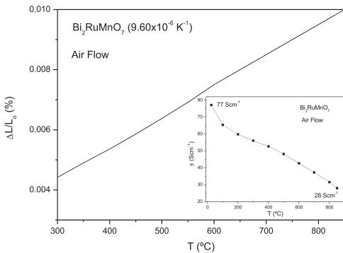
Fig. 7. Thermal expansion determined by dilatometry for \( Bi_{2}RuMnO_{7} \) . The inset shows the thermal evolution of the electrical conductivity of the \( Bi_{2}RuMnO_{7} \) .

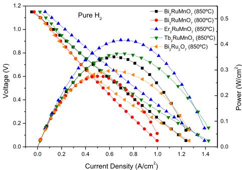
Fig. 8. Cell voltage (left axis) and power density (right axis) as a function of the current density for the test cell with the configuration SMFO/LDC/LSGM/BRMO in pure \( H_{2} \) measured at \( T = 800 \) and \( 850^{\circ}C \) . The performance at \( 850^{\circ}C \) is compared to that of the \( R_{2}RuMnO_{7} \) oxides cathodes and \( Bi_{2}Ru_{2}O_{7} \) .
illustrates the considered model for the magnetic structure. At 2 K the magnetic moments at \( (\mathrm{Ru},\mathrm{Mn}) \) octahedral sites is \( 1.78(2)\mu_{\mathrm{B}} \) .
3.4. Thermal expansion and electrical conductivity measurements
Aiming to determine the mechanical compatibility of our material with the other cell components, thermal expansion measurements of the dense ceramic were carried out in an air atmosphere. The thermal expansion was measured in sintered pellets, heated in air at \( 900\ ^{\circ}C \) for 12 h. A dilatometric analysis was performed between 35 and \( 850\ ^{\circ}C \) for several cycles; the data were only recorded during the heating runs. Fig. 7 shows no abrupt changes in the thermal expansion of \( Bi_{2}RuMnO_{7} \) in all the temperature range under measurement. The TEC measured under air atmosphere between 300 and \( 850\ ^{\circ}C \) is \( 9.60\times10^{-6}\ K^{-1} \) ; this value perfectly matches those usually displayed by SOFC electrolytes.
The inset of Fig. 7 shows the thermal variation of the electrical conductivity of \( Bi_{2}RuMnO_{7} \) measured in sintered bars in air atmosphere by the dc four-probe method. The pyrochlore oxide shows a metallic-like conductivity under oxidizing conditions in all the temperature range; for instance \( \sigma = 77\ Scm^{-1} \) at \( 50\ ^{\circ}C \) and

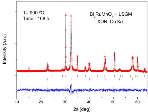
Fig. 9. Rietveld-refined XRD profiles of a mixture of LSGM and \( Bi_{2}RuMnO_{7} \) after a thermal treatment at \( 900\;^{\circ}C \) in air, showing no reaction products between both phases other than the initial reactants. The first and second series of Bragg positions correspond to \( Bi_{2}RuMnO_{7} \) and LSGM, respectively.
28 Scm \( ^{-1} \) at 850 °C. At the SOFC working temperature, between 650 and 850 °C, the values are also high and span from 39 to 28 Scm \( ^{-1} \) . The behavior of this pyrochlore is similar to that of Bi \( _{2} \) Ru \( _{2} \) O \( _{7} \) oxide, which exhibits an increase in the electrical resistance with temperature indicating a "metallic"-type behavior [4], which is in agreement with the model of Sleight and Bouchard [31].
However the \( Bi_{2}RuMnO_{7} \) behavior is opposite to that observed for the other \( R_{2}RuMnO_{7} \) pyrochlores (R = rare earths) that present a semiconductor-like behavior [17]. As suggested for \( Bi_{2}Ru_{2}O_{7} \) , the hybridization of Bi and Ru states present at the Fermi energy leads to a wider conduction band relative to pyrochlores with lanthanide A-site elements; this comparatively large \( Ru:4d \) bandwidths appear to result from covalent mixing between \( Ru:4d \) and \( Bi:6s \) orbitals. For example \( Y_{2}Ru_{2}O_{7} \) and \( Ln_{2}Ru_{2}O_{7} \) are insulating while isoelectronic \( Bi_{2}Ru_{2}O_{7} \) and \( Pb_{2}Ru_{2}O_{6.5} \) are weakly metallic. In the present case, a strong hybridization of the \( 6s^{2} \) lone pair electrons of the \( Bi^{3+} \) cations with the O 2p and Ru 4d states may be in the origin of the metallic conductivity and excellent charge transport in \( Bi_{2}RuMnO_{7} \) , at difference with the structurally-related \( R_{2}RuMnO_{7} \) (R = rare earth) pyrochlore oxides.
3.5. Fuel-cell tests
The performance of \( Bi_{2}RuMnO_{7} \) pyrochlore was tested as cathode material in single cells in an electrolyte-supported configuration using a 300- \( \mu \) m-thick LSGM electrolyte. Fig. 8 illustrates the cell voltage and power density as a function of the current density at 800 and 850 °C for the single cell fed with pure \( H_{2} \) . The maximum power densities generated by the cell are 277 mW cm \( ^{-2} \) and 360 mW cm \( ^{-2} \) , respectively. The present performance opens the possibility of considering this material as cathode for SOFCs.
In order to compare the performance of our \( Bi_{2}RuMnO_{7} \) cathode with the other family members, identical single cells with \( R_{2}RuMnO_{7} \) (R = Er and Tb [17]) as cathode were also built and evaluated. It is noteworthy that the values obtained with \( Bi_{2}RuMnO_{7} \) as cathode are lower than those determined for the other compounds of the rare-earth-containing family; from the curves represented in Fig. 8 the maximum power densities are \( 415\ mW\ cm^{-2} \) and \( 365\ mW\ cm^{-2} \) for Er and Tb, respectively, at \( 850\ ^{\circ}C \) . Although \( Bi_{2}RuMnO_{7} \) exhibits higher electronic conductivity values at the working temperature ( \( 650-850\ ^{\circ}C \) ), the presence of oxygen vacancies in the \( R_{2}RuMnO_{7} \) pyrochlores, absent in the Bi analog, provide them with the ionic mobility required for MIEC oxides in SOFCs, the oxygen vacancies being responsible for the \( O^{2-} \) -ion transport. This result highlights the importance of implementing both features (electronic + ionic transport) for optimum performance in cathode materials. The design and preparation of chemically modified cathodes based upon \( Bi_{2}RuMnO_{7} \) with a superior concentration of O2-type vacancies, in compositions such as \( Bi_{2}RuMn_{1-x}M_{x}O_{7-x/2} \) (M = trivalent first-row transition metal; typically \( Fe^{3+} \) or \( Cr^{3+} \) ) is under development.
It was also interesting to compare the performance of our \( Bi_{2}RuMnO_{7} \) material with the parent \( Bi_{2}Ru_{2}O_{7} \) pyrochlore oxide. Several studies have been previously performed in order to evaluate this oxide as cathode for SOFC operating at intermediate temperatures [32,33]. Takeda et al. [34] obtained low polarization resistances with YSZ as electrolyte. Other authors report that this oxide reacts with \( Ce_{0.9}Gd_{0.1}O_{1.95} \) (CGO) electrolyte powders at 900 °C and cannot be considered as appropriate cathode material for CGO [33]. On the other hand, the performance of \( Bi_{2}Ru_{2}O_{7} \) as cathode in single cells has not been described in the literature. For this reason, in the present work we considered interesting to test \( Bi_{2}Ru_{2}O_{7} \) pyrochlore as cathode material in single cells in similar conditions to those implemented for \( Bi_{2}RuMnO_{7} \) . In an electrolyte-supported configuration on LSGM we obtained for \( Bu_{2}Ru_{2}O_{7} \) a poorer performance than that determined for \( Bi_{2}RuMnO_{7} \) ; from the curve represented in Fig. 8 the maximum power density obtained is \( 294\ mW\ cm^{-2} \) at \( 850\ ^{\circ}C \) . It can be noted that the introduction of Mn in the B-sublattice improves the power output of the cell with this pyrochlore as electrode material in SOFC.
The performance of our material as cathode in an SOFC has also been compared with the power densities obtained for other alternative cathodes. The literature gathers some cathodes exhibiting much poorer power densities than \( Bi_{2}RuMnO_{7} \) ; for example, the power density using \( LaSr_{3}Fe_{3-y}Co_{y}O_{10-\delta} \) , at \( 800\ ^{\circ}C \) attained a value lower than \( 240\ mW\ cm^{-2} \) , presenting almost the same power density than the well-known perovskite \( La_{0.6}Sr_{0.4}CoO_{3-\delta} \) as cathode [35]. Another reference example is the performance of the commercial cells with a \( (\mathrm{La},\mathrm{Sr})\mathrm{MnO}_{3}-\mathrm{YSZ} \) composite cathode and Ni–YSZ anode, yielding a power density of about \( 260\ mW\ cm^{-2} \) at \( 850\ ^{\circ}\mathrm{C} \) using hydrogen as fuel [36]. Of course there are other cathodes that exhibit higher power densities than our pyrochlore; for instance, a single cell with \( Ca_{2}Co_{2}O_{5} \) (CCO) oxide as cathode was described to exhibit a power density of \( 522\ mW\ cm^{-2} \) at \( 800\ ^{\circ}\mathrm{C} \) in \( H_{2} \) fuel [37]. For \( SrCo_{0.95}Sb_{0.05}O_{3-\delta} \) as the cathode, the test cells gave a maximum power density of 511 and \( 618\ mW\ cm^{-2} \) for temperatures of 800 and \( 850\ ^{\circ}C \) , respectively, with pure \( H_{2} \) as fuel and air as oxidant [38]. This comparison with other cathodes described in the literature demonstrates that our pyrochlore performs as a reasonable cathode for SOFC.
3.6. Chemical compatibility and scanning electron microscopy
The chemical compatibility of \( Bi_{2}RuMnO_{7} \) with the LSGM electrolyte has also been checked by firing mixtures of both powdered materials at \( 900\;^{\circ}C \) in air for 168 h (1 week); Fig. 9 shows a Rietveld analysis of the product, consisting in a mixture of both unaltered pyrochlore and perovskite phases, demonstrating that there is no measurable chemical reaction between both oxides.
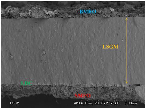
Fig. 10 shows the cross-section micrographs of the anode–electrolyte–cathode interface after the single-cell tests for \( Bi_{2}RuMnO_{7} \) analyzed by Scanning Electron Microscopy (SEM). The SEM image shows a uniform and dense electrolyte layer, without cracks or fractures. It is estimated that the thicknesses of the BRMO layer are approximately \( 10 \mu m \) and the average grain sizes of the particles are about \( 1 \mu m \) . In addition, the BRMO exhibits a good porosity, which is one of the essential requirements for optimal cathode materials.

Fig. 10. SEM micrographs of the cross-section of the anode–electrolyte–cathode interface after the single-cell test.
4. Conclusions
We have shown that \( Bi_{2}RuMnO_{7} \) oxide exhibits a cubic pyrochlore structure (Fd-3m space group) with a singular feature, unveiled by neutron diffraction, concerning a significant degree of disorder of Mn and Bi between A and B positions. Part of Bi ions occupies the octahedral sublattice in a pentavalent oxidation state; a fraction of Mn ions, in divalent state, are located at the voluminous A scalenohedral coordination cages. The magnetic structure, solved from low-temperature NPD data, shows a collinear AFM coupling between Mn/Ru cations at the B sublattice, split in two subsets of Mn/Ru moments antiferromagnetically coupled to each other. The electrical characterization evidences a metallic behavior in the \( Bi_{2}RuMnO_{7} \) oxide, in contrast to the other \( R_{2}RuMnO_{7} \) pyrochlores (R = rare earths) that are semiconductors. The thermal expansion coefficient is \( 9.60 \times 10^{-6} K^{-1} \) , very close to those of the usual SOFC electrolytes at these temperatures. All these features make the pyrochlore with \( Bi_{2}RuMnO_{7} \) composition to be considered as candidate for cathode in SOFCs: in single SOFCs with LSGM as electrolyte, a maximum power density of 277 and 360 mW cm \( ^{-2} \) was obtained at 800 and 850 °C with pure \( H_{2} \) as fuel, respectively.
Acknowledgments
We thank the financial support of the Spanish Ministry of Education to the projects MAT2010-16404 and we are grateful to the Institut Laue-Langevin (ILL) for making all facilities available.
Appendix A. Supplementary material
Supplementary material associated with this article can be found, in the online version, at http://dx.doi.org/10.1016/j.jpowsour.2013.08.125.
References
[1] M.A. Subramanian, G. Aravamudan, G.V. Subba Rao, Prog. Solid State Chem. 15 (1983) 55.
[2] J.A. Díaz-Guillén, M.R. Díaz-Guillén, K.P. Padmasree, A.F. Fuentes, J. Santamaría, C. León, Solid State Ionics 179 (2008) 2160–2164.
[3] P.J. Wilde, C.R.A. Catlow, Solid State Ionics 112 (3–4) (1998) 173–183.
[4] R.E. Carbonio, J.A. Alonso, J.L. Martinez, J. Phys. Condens. Matter 11 (1999) 361–369.
[5] H.S. Horowitz, J.M. Longo, H.H. Horowitz, J.T. Lewandowski, Solid State Chem. Catal. 279 (1985) 143.
[6] H.S. Horowitz, J.M. Longo, H.H. Horowitz, j. Electrochem. Soc. 130 (1983) 1851.
[7] R.G. Edgell, J.B. Goodenough, A. Hamnett, C.C. Naish, J. Chem. Soc. Faraday Trans. I 79 (1983) 893.
[8] H.S. Harret, A.W. Sleight, J.F. Weiher, J.L. Gillson, C.G. Frederick, G.A. Jones, R.S. Swingle, D. Swatzfager, J.E. Gulley, P.C. Hoell, Valence Instabilities and Related Narrow Band Phenomena, 1977, pp. 545.
[9] W.Y. Hsu, R.V. Kasowski, T. Miller, T.C. Chiang, Appl. Phys. Lett. 52 (1988) 7.
[10] P.A. Cox, J.B. Goodenough, P.J. Tavener, D. Telles, G. Edgell, J. Solid State Chem. 62 (1986) 360.
[11] C. Iwakura, T. Edamoto, H. Tamura, Bull. Chem. Soc. Jpn. 59 (1986) 145.
[12] M. Ito, Y. Yasui, M. Kanada, H. Harashina, S. Yoshii, K. Murata, M. Sato, H. Okumura, K.J. Kakurai, J. Phys. Chem. Solids 62 (1–2) (2001) 337.
[13] C. Bansal, H. Kawanaka, H. Bando, Y. Nishihara, Phys. Rev. B 66 (2002) 052406.
[14] Y. Shimakawa, Y. Kubo, T. Manako, Nature 379 (1996) 53–55.
[15] Y. Shimakawa, Y. Kubo, Mater. Sci. Eng. B 63 (1–2) (1999) 44–48.
[16] M. Retuerto, M.J. Martínez-Lope, C. de la Calle, R. Martínez-Coronado, M. García-Hernández, M.T. Fernández, J.A. Alonso, J. Appl. Phys. 107 (9) (2010) 093919–093919-7.
[17] R. Martínez-Coronado, A. Aguadero, C. de la Calle, M.T. Fernández-Díaz, J.A. Alonso, J. Power Sources 196 (2011) 4181–4186.
[18] R. Martínez-Coronado, M. Retuerto, M.T. Fernández, J.A. Alonso, Dalton Trans. 41 (2012) 8575.
[19] R. Martínez-Coronado, J.A. Alonso, A. Aguadero, M.T. Férnández-Díaz, J. Power Sources 208 (2012) 153–158.
[20] H.M. Rietveld, J. Appl. Crystallogr. 2 (1969) 65–71.
[21] J. Rodríguez-Carvajal, Phys. B 192 (1993) 55–69.
[22] F. Beech, W. Michaela Jordan, C.R.A. Catlow, J. Solid State Chem. 77 (1988) 322–335.
[23] R.A. Beyerlein, H.S. Horowitz, J.M. Longo, M.E. Leonowicz, J. Solid State Chem. 51 (1984) 253–265.
[24] K.B. Tan, C.C. Khaw, C.K. Lee, Z. Zainal, G.C. Miles, J. Alloys Compd. 508 (2) (2010) 457–462.
[25] R.S. Roth, T.A. Vanderah, P. Bordet, I.E. Grey, W.G. Mumme, L. Cai, J.C. Nino, J. Solid State Chem. 181 (2008) 406–414.
[26] P. García Casado, J.A. Alonso, J.L. Martínez, M.T. Fernández, I. Rasines, Chem. Mater. 12 (5) (2000) 1217–1221.
[27] M.J. Whitaker, J.F. Marco, F.J. Berry, C. Taith, E. Blackburn, C. Greaves, J. Solid State Chem. 198 (2013) 316.
[28] M.C. Blanco, D.G. Franco, Y. Jalit, E.V. Pannuzino Minier, G. Berndt, A. Paesano Jr., G. Nieva, R.E. Carbonio, Phys. B Condens. Matter 407 (2012) 3078–3080.
[29] R. Kanno, Y. Takeda, T. Yamamoto, Y. Kawamoto, O. Yamamoto, J. Solid State Chem. 102 (1993) 106–114.
[30] R.D. Shannon, Acta Crystallogr. A 32 (1976) 751–767.
[31] A.W. Sleight, R.J. Bouchard, Solid State Chem. 6 (1972) 364.
[32] Abhishek Jaiswal, Ching-Tang Hu, Eric D. Wachsman, J. Electrochem. Soc. 154 (10) (2007) 1088–1094.
[33] J.M. Bae, B.C.H. Steele, J. Electroceram. 3 (1) (1999) 37–46.
[34] T. Takeda, R. Kanno, Y. Kawamoto, Y. Takeda, O. Yamamoto, J. Electrochem. Soc. 147 (2000) 1730.
[35] K.T. Lee, A. Manthiram, Chem. Mater. 18 (6) (2006) 1621–1626.
[36] Toshio Suzuki, Masanobu Awano, Piotr Jasinski, Vladimir Petrovsky, Harlan U. Anderson, Solid State Ionics 177 (19–25) (2006) 2071–2074.
[37] T. Wei, Y.-H. Huang, L. Jiang, J.-Y. Yang, R. Zeng, J.B. Goodenough, RSC Adv 3 (2013) 2336–2340.
[38] A. Aguadero, J.A. Alonso, D. Perez-Coll, C. de la Calle, M.T. Fernandez-Diaz, J.B. Goodenough, Chem. Mater. 22 (2010) 789–798.
 p3_0.jpg
 p3_1.jpg
 p4_0.jpg
 p4_1.jpg
 p4_2.jpg
 p5_0.jpg
 p5_1.jpg
 p5_2.jpg
 p5_3.jpg
 p6_0.jpg